
Display device

A technology for display devices and display screens, which can be applied to identification devices, instruments, televisions, etc., can solve problems such as large-scale limitations and difficulty in coping with the improvement of display resolution, and achieve the effect of suppressing cracks and maintaining manufacturing characteristics.

Inactive Publication Date: 2015-02-25
SONY CORP
View PDF11 Cites 10 Cited by
  • Summary
  • Abstract
  • Description
  • Claims
  • Application Information

AI Technical Summary

Problems solved by technology

The reason for this is as follows: Although the image source is a planar image in one plane cut from space, the cathode ray tube involves convex conversion, has limitations in upsizing, or is difficult to cope with an increase in display resolution

Method used


Image

  • Display device
  • Display device
  • Display device

Examples


Embodiment approach

[0036] (structure)

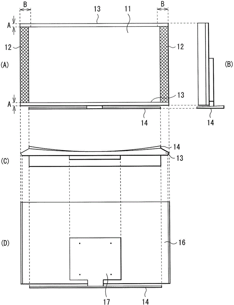
[0037] figure 1 The appearance of a display device (display device 1 ) of one example of the present invention when viewed from the front side is shown. figure 2 (A) to (D) are respectively a front view, a side view, a top view and a rear view of the display device 1 . The display device 1 can be used, for example, as a television, and a main body portion including a display panel (liquid crystal panel 11 ) is supported by a stand (stand 14 ) and held in a predetermined posture. Therefore, the display device 1 can be used in a fixed form, that is, arranged on a horizontal surface such as a floor, a shelf or a desktop; but it can also be used in a wall-mounted form. In the wall-mounted state, the bracket 14 is separated from the main body.

[0038] The display device 1 includes, for example, speaker sections 12 (sound output means) located at ends (here, right and left ends in the X direction) along one axis of the liquid crystal panel 11 . Decorative p...


PUM


Abstract

A display device is equipped with a display panel that includes a display screen that is concave, in which a cross-section of the display panel along one axial direction has a curved shape, and the radius of curvature (R) of the curved shape of the display screen is larger than 2000 mm.

Description

technical field [0001] The invention relates to a display device suitable for equipment such as large-size television sets. Background technique [0002] Display devices such as television receivers or personal computer (PC) monitors have transitioned from cathode ray tubes to flat panel displays (FPDs), typically liquid crystal or plasma displays, and currently FPDs. The reason for this is as follows: Although the image source is a planar image in one plane cut out from space, a cathode ray tube involves convex conversion, has limitations in upsizing, or is difficult to cope with an increase in display resolution. [0003] For example, in this kind of FPD, the display screen body including the display screen is supported in a predetermined posture by a stand or the like, and speakers are arranged on the right and left sides of the display screen (for example, Patent Documents 1 and 2). [0004] reference list [0005] patent documents [0006] Patent Document 1: JP 42533...

Claims


Application Information

Patent Timeline
Patent Type & Authority Applications(China)
IPC IPC(8): H04N5/64G09F9/00G09F9/30H04N5/66
CPCG02F1/1333G06F1/1601G02F2201/56H04N5/64G02F1/133314G02F1/133308G02F1/133615
Inventor 永谷真平
Owner SONY CORP
Learn More