
Three-dimensional measurement apparatus, and three-dimensional measurement method

A technology for three-dimensional measurement and object measurement, applied in the field of three-dimensional measurement

Inactive Publication Date: 2015-02-25
SHIMA SEIKI MFG LTD
View PDF8 Cites 10 Cited by
  • Summary
  • Abstract
  • Description
  • Claims
  • Application Information

AI Technical Summary

Problems solved by technology

However, this method requires a mechanism to move the grid in the vertical direction (projection direction) relative to the projector.

Method used


Image

  • Three-dimensional measurement apparatus, and three-dimensional measurement method
  • Three-dimensional measurement apparatus, and three-dimensional measurement method
  • Three-dimensional measurement apparatus, and three-dimensional measurement method

Examples


Embodiment

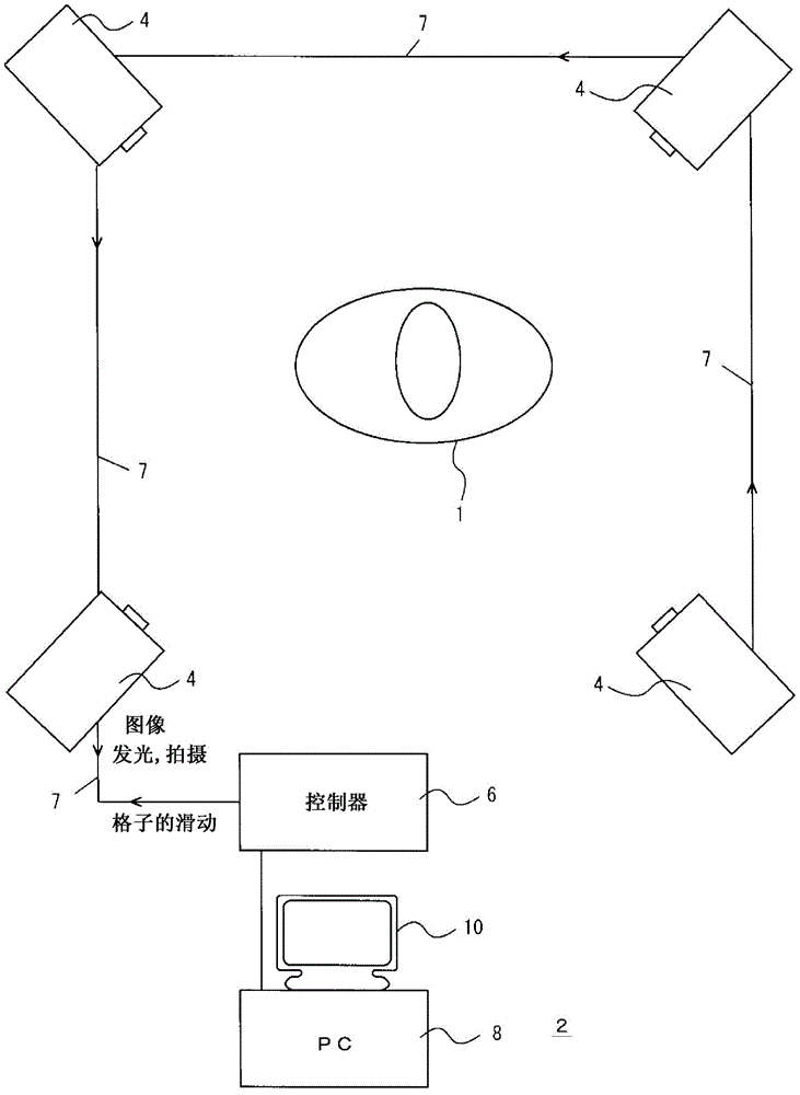
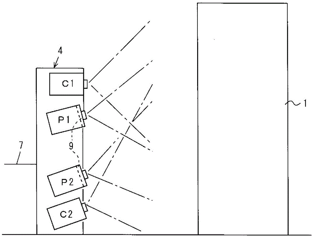
[0035] Figure 1 to Figure 8 In , the three-dimensional measuring device 2 and the three-dimensional measuring method of the embodiment are shown. figure 1 Here, 4 is a unit for grid projection and imaging, for example, four units are arranged around an object to be measured (hereinafter referred to as a measurement object) 1 . The measurement object 1 is, for example, a human body, furniture, machinery, automobiles, electronic equipment, buildings, etc., and four units 4 are installed to three-dimensionally measure the entire circumference of the measurement object 1 . When measuring the entire circumference, for example, three or more and six or less units 4 are provided, and if only one surface is measured, one unit may be used. 6 is a controller, which controls the movement of the grid in the unit 4, the lighting of the projector, and the shooting by the camera, and sends instructions related to them to the unit 4 via the LAN 7. In addition, the unit 4 sends the capture...


PUM


Abstract

A lattice is shifted and projected several times from projectors onto an object to be measured, the object to be measured having the lattice projected thereon is imaged by cameras, and conversion into a three-dimensional shape of the object to be measured is performed. A projector is provided at a position near to the cameras, and a projector is provided at a position far from the cameras. A phase obtained from images acquired during projection from the projector at the position near to the cameras is used to convert, into a phase uniquely expressing a position along the light-of-sight direction from the cameras, a phase obtained from images acquired during projection from the projector at the position far from the cameras. As a result, the three-dimensional shape of an object can be accurately measured in a short period of time.

Description

technical field [0001] The present invention relates to three-dimensional measurement, and in particular to the connection of phases obtained by phase shifting. Background technique [0002] The three-dimensional shape of the object to be measured (hereinafter simply referred to as "the object to be measured") is obtained by projecting a grid from a projector onto the object to be measured and capturing an image with a camera (for example, Patent Document 1: Japanese Patent No. 3536097). A grid whose light transmittance changes periodically in a sinusoidal wave is arranged on the front surface of the projector, and the positions of the grids are moved at intervals of, for example, 1 / 4 of the cycle of the sinusoidal wave, for example, four shots are performed. Assuming that the luminance of the same pixel in the four images is I0-I3, (I1-I3) / (I0-I2) represents the phase of the pixel with respect to the grid, and the phase represents the direction of the measurement object obs...

Claims


Application Information

Patent Timeline
Patent Type & Authority Applications(China)
IPC IPC(8): G01B11/25
CPCG01B11/25G01B11/2527G06T7/62H04N13/204H04N13/296G01B11/2513G01B11/2545G06T2207/10028G06T2207/20068
Inventor 岩井一能
Owner SHIMA SEIKI MFG LTD
Learn More