
Open shell and tube condenser

A shell-and-tube condenser technology, which is applied in the field of mechanical devices, can solve the problems of reduced condensation effect, inconvenient collection, and inability to detect corrosion of condenser heat transfer tubes in time, and achieve the effect of increasing height and facilitating discharge

Inactive Publication Date: 2015-02-25
常州麦克斯威机械有限公司
View PDF0 Cites 1 Cited by
  • Summary
  • Abstract
  • Description
  • Claims
  • Application Information

AI Technical Summary

Problems solved by technology

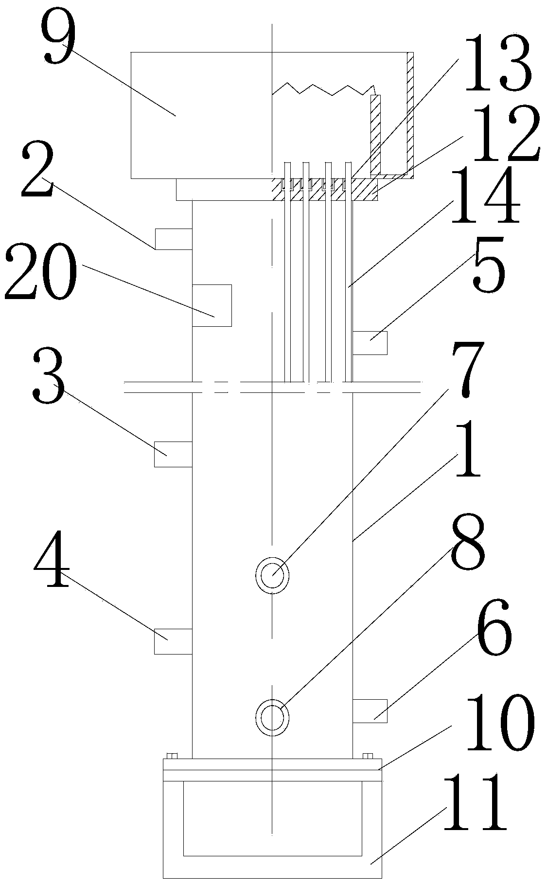
[0002] Shell and tube condenser, also known as heat exchanger, is a heat transfer tool that can effectively transfer heat. It is used as a heat removal device and hot water supply device for air-conditioning refrigeration units and industrial equipment; It is widely used in industrial equipment, but this vertical shell-and-tube condenser has the following disadvantages: 1) It is impossible to observe the internal conditions of the condenser, and it is impossible to find that the internal heat transfer tubes of the condenser are corroded in time, and the condensation effect will be reduced after long-term use. 2) Since the outlet pipe is set at the bottom of the condenser, it is not convenient to collect

Method used


Image

  • Open shell and tube condenser
  • Open shell and tube condenser
  • Open shell and tube condenser

Examples


Embodiment 1

[0018] see Figure 1-Figure 4 As shown, it includes a cylindrical shell 1, one side of the shell is respectively provided with a safety valve joint 2, a pressure equalizing pipe 3, and an air release pipe 4 from top to bottom, and the other side is respectively provided with an inlet pipe from top to bottom. Air pipe 5 and liquid outlet pipe 6; the front side of the housing is provided with a pressure gauge 7 and an oil discharge pipe 8 respectively from top to bottom, a water distribution tank 9 is provided at the top of the housing, and a base 10 is provided at the bottom of the housing; Both sides of the base are connected to the support frame 11; a condensing device is provided in the housing, and the condensing device includes a tube plate 12 arranged at both ends of the housing, and a plurality of mounting holes 13 are opened on the tube plate, and the mounting holes are installed There are heat transfer tubes 14; the top of the housing is provided with a perspective win...

Embodiment 2

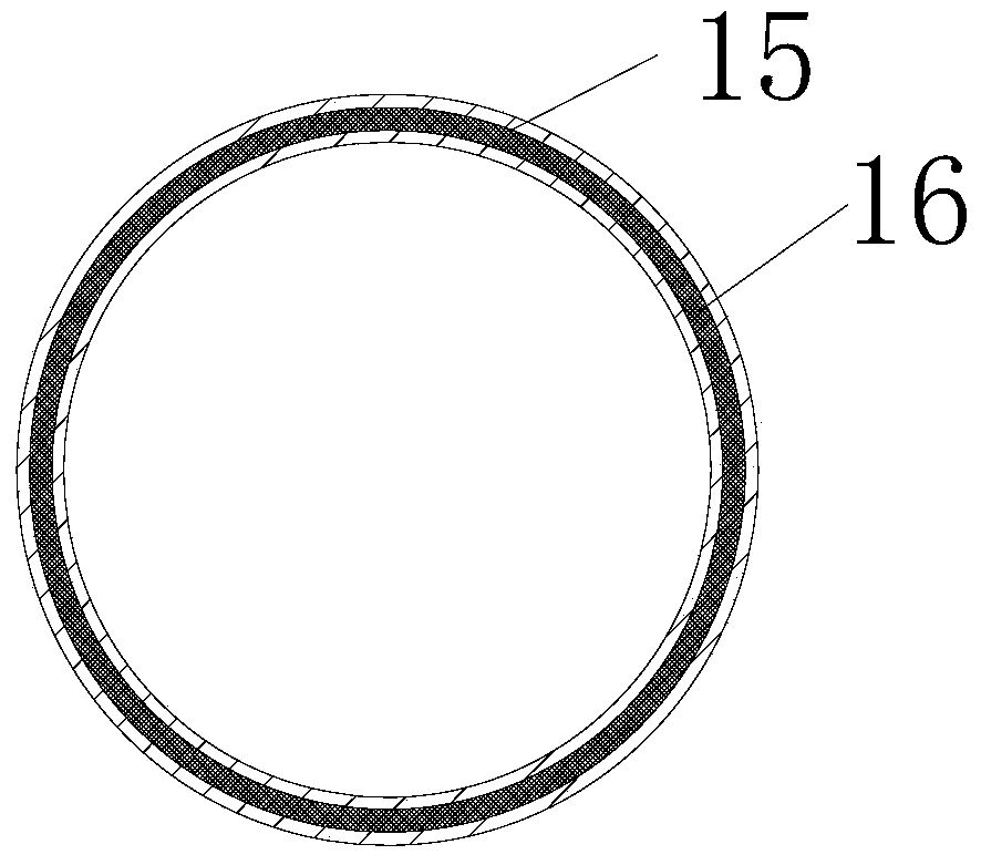
[0023] On the basis of the foregoing embodiments, an annular groove 15 is provided on the end surface of the housing along its length direction, and a damping interlayer 16 is provided in the annular groove. The damping interlayer is arranged in the annular groove, which is beneficial to shock and noise reduction.

[0024] Preferably, the damping interlayer adopts rubber and plastic damping plates.

Embodiment 3

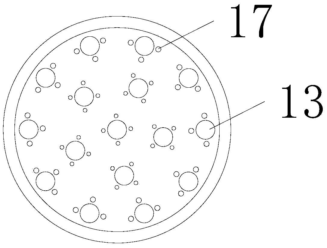
[0026] On the basis of Embodiment 1, several return holes 17 are provided around the installation holes on the tube plate. The combination of the return hole and the installation hole will form a turbulent flow when the cooling water passes through the return hole, and ensure the flow rate of the cooling water, so that the heat exchange of the cooling water is more sufficient, thereby improving the condensation efficiency of the condenser.

[0027] Preferably, the diameter of the return hole is 4-7mm. When the diameter of the return hole is 4-7 mm, the effect of generating turbulent flow is better.


PUM

PropertyMeasurementUnit
Diameteraaaaaaaaaa

Abstract

The invention relates to the technical field of mechanical devices, in particular to an open shell and tube condenser. A cylindrical shell is arranged, a safety valve connector, a balance pipe and an exhaust pipe are arranged on one side of the shell from top to bottom, and a gas inlet pipe and a liquid outlet pipe are arranged on the other side of the shell from top to bottom; a pressure gauge and an oil discharge pipe are arranged on the front side of the shell from top to bottom. The open shell and tube condenser is characterized in that a water distribution tank is arranged at the top end of the shell, and a base is arranged at the bottom of the shell; the two sides of the base are connected with a supporting frame; a condensation device is arranged in the shell and comprises tube plats arranged at the two ends of the shell, a plurality of installing holes are formed in the tube plates, and heat transfer tubes are installed in the installing holes; a perspective window is installed on the shell. Therefore, the internal conditions of the open shell and tube condenser can be observed, and condensed liquid can be conveniently collected.

Description

technical field [0001] The invention relates to the technical field of mechanical devices, in particular to a vertical shell-and-tube condenser. Background technique [0002] Shell and tube condenser, also known as heat exchanger, is a heat transfer tool that can effectively transfer heat. It is used as a heat removal device and hot water supply device for air-conditioning refrigeration units and industrial equipment; It is widely used in industrial equipment, but this vertical shell-and-tube condenser has the following disadvantages: 1) It is impossible to observe the internal conditions of the condenser, and it is impossible to find that the internal heat transfer tubes of the condenser are corroded in time, and the condensation effect will be reduced after long-term use. 2) Since the outlet pipe is arranged at the bottom of the condenser, it is not convenient to collect. Contents of the invention [0003] The object of the present invention is to provide a vertical she...

Claims


Application Information

Patent Timeline
IPC IPC(8): F28B1/02
Inventor 顾建忠
Owner 常州麦克斯威机械有限公司
Learn More