
Warp stopping bar middle supporting frame structure

A bracket structure and warp slat technology, applied in textiles, textiles, papermaking, looms, etc., can solve the problems of limited space, the pull-out of the drop-off slats, and the slow removal of the drop-off slats 2, etc., to achieve convenient manufacturing. , the effect of eliminating friction and shortening standby time

Inactive Publication Date: 2015-02-25
CHANGSHU CHANG XIN TEXTILE EQUIP
View PDF12 Cites 7 Cited by
  • Summary
  • Abstract
  • Description
  • Claims
  • Application Information

AI Technical Summary

Problems solved by technology

Yet because the menopause strip supporting plate 2 is rested on the menopause strip supporting plate 2, thereby the menopause strip supporting plate 2 cannot be pulled out upwards, and the menopause strip supporting plate 2 can only be pulled downward. Bar supporting plate 3, therefore must first remove the blockage of the opening of the warp creel matching chamber 111 by the limit pressing block 112 and lead the warp creel fixing plate 1 together with the spacer supporting plate 3 downwards, at this time, although the spacer has withdrawn The spacer support groove 31, but because the two ends of the spacer are still in the state fixed with the menopause strip holder (can refer to CN202954203U), although the bottom of the menopause strip supporting plate 2 length direction can be connected with the length of the spacer strip supporting plate 3 The upper part of the direction is separated (previously, the two were in a state of mortise and tenon fit), but the space for the menacea supporting plate 2 to be pulled downward is very limited, because there is an obstacle of the spacer, so the menacea supporting plate can only be pulled 2. The state of tilting to one side makes the menacea withdraw from the support groove 21, that is, the menacea supporting plate 2 is unloaded.
It can be seen that the unloading of the warp drop supporting plate 2 is very slow, and it is the same during installation.

Method used


Image

  • Warp stopping bar middle supporting frame structure
  • Warp stopping bar middle supporting frame structure
  • Warp stopping bar middle supporting frame structure

Examples


Embodiment

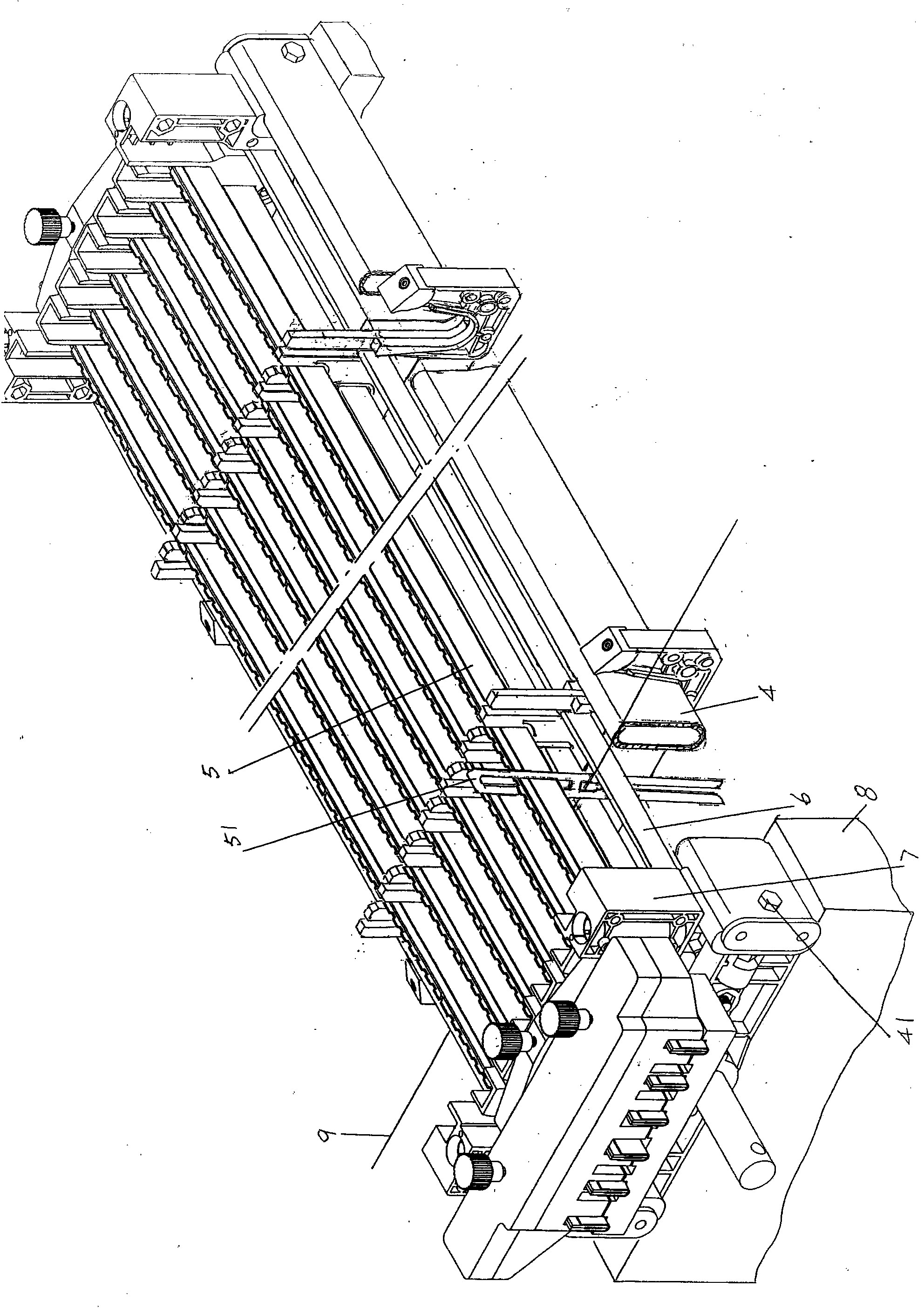
[0026] See figure 1 , provides a warp creel fixing plate 1 that preferably adopts plastics and is obtained through mould-making, respectively integrally forms a warp creel fixing plate seat 11 at the left end and the right end of this warp creel fixing plate 1, on the warp creel fixing plate seat 11 The upward position (i.e. the upward side) constitutes a U-shaped warp frame 4 ( figure 2 Show) matching warp creel matching cavity 111. because figure 2 The cross-sectional shape of the shown warp creel 4 is generally oval, so the warp creel matching chamber 111 is designed as U-shaped, but if the cross-sectional shape of the warp creel 4 is changed for the purpose of avoiding the design of the present invention, And if the shape of the warp creel matching chamber 111 is also adapted, it should be regarded as an equivalent replacement and still belongs to the scope of the disclosed technical content of the present invention. Depend on figure 1 As shown, on the top of the f...


PUM


Abstract

The invention discloses a warp stopping bar middle supporting frame structure and belongs to the technical field of spinning device accessories. The warp stopping bar middle supporting frame structure comprises a warp frame fixing plate and a warp stopping bar supporting plate, the left end and the right end of the warp frame fixing plate each form a warp frame fixing plate base, the tops of warp frame matching cavities are provided with limiting pressing blocks, and the upper portion of the warp stopping bar supporting plate is provided with warp stopping bar supporting grooves. The warp stopping bar middle supporting frame structure is characterized in that bar separation grooves are formed in the upper portion of the warp stopping bar supporting plate in the length direction, and the bar separation grooves and the warp stopping bar supporting grooves are distributed in an alternating mode, wherein the depth of the bar separation grooves is larger than that of the warp stopping bar supporting grooves. Supporting plate inserting grooves are formed in the warp frame fixing plate bases, the supporting plate inserting grooves stretch into the bottoms of the warp frame matching cavities, the edge parts of the left end and the right end of the warp stopping bar supporting plate are matched with the supporting plate inserting grooves, the lower portions of the edge parts of the left end and the right end of the warp stopping bar supporting plate stretch to form supporting plate pressing feet, and the supporting plate pressing feet correspond to the bottoms of the warp frame matching cavities. The structure is simplified, manufacturing is convenient, the influences on warp stopping bars are avoided, the friction between the warp supporting bar supporting plate and the warp frame fixing plate bases is eliminated, the working intensity is relieved, and the standby time is shortened.

Description

technical field [0001] The invention belongs to the technical field of textile equipment accessories, and in particular relates to a bracket structure for menopause strips. Background technique [0002] The above-mentioned menopause middle bracket is also called the menopause middle support plate, which is an auxiliary part of the warp menace, and it is fixed on the warp creel in use to support (support) the warp menace, preventing the lengthy menace from deflection. And at the same time, it can stabilize the warp strips, for example, keep the parallel spacing between adjacent warp strips consistent. The function of the aforesaid menopause strips is to wear the menopause strips, each warp strip passes through a warp yarn, and the warp yarns make the menopause strips in a suspended state on the menopause strips, so that the chip on the menopause strips and the iron clad are in a state of being in the air. Non-conductive state (the chip and the iron-clad are usually separate...

Claims


Application Information

Patent Timeline
Patent Type & Authority Applications(China)
IPC IPC(8): D03D51/20
CPCD03D51/20
Inventor 陈玉升
Owner CHANGSHU CHANG XIN TEXTILE EQUIP
Learn More