
Automatic mold drawing machine for wheel casting mold

A technology for casting molds and ejectors, applied in the field of automatic ejectors, can solve problems such as ejector sticking, affecting production efficiency, mold damage, etc., so as to increase the contact area, improve production efficiency, and facilitate removal and placement. Effect

Active Publication Date: 2015-02-25
ZHEJIANG WANFENG AUTO WHEEL
View PDF6 Cites 1 Cited by
  • Summary
  • Abstract
  • Description
  • Claims
  • Application Information

AI Technical Summary

Problems solved by technology

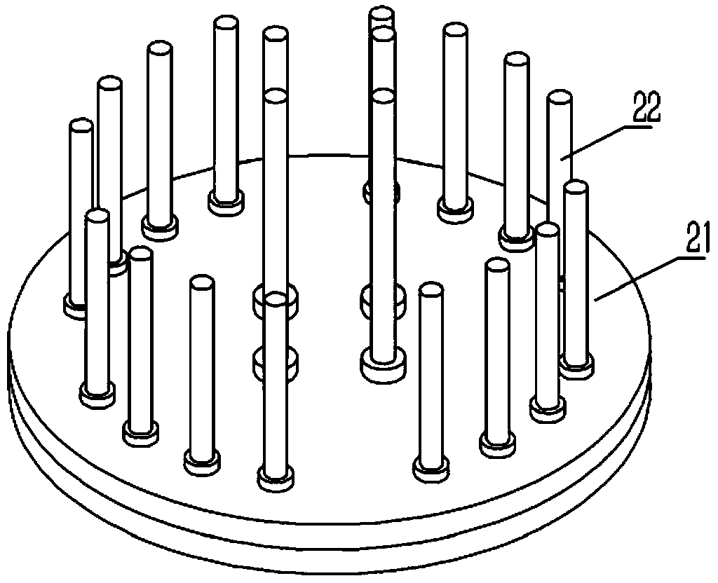
[0002] At present, the wheel hub is generally formed by casting, and after the casting mold completes a production cycle, it needs to be fully maintained and repaired. It is necessary to disassemble the screw, top and bottom plates of the upper mold and other important links. The mold installation of the existing upper mold Seat such as figure 1 As shown, it is inserted into the screw rod 21 of the mold mounting seat, but due to the influence of high temperature and high pressure, the ejector pin is generally stuck, and the disassembly of the mold requires all the screws and ejector pins to be separated, or the mold must be manually clamped with an iron bar. The top plate needs to be knocked continuously to complete the disassembly, and the disassembly process will cause serious damage to the employee's body (especially the psoas) and the mold
In addition, it takes more than 40 minutes to disassemble each pair of molds. On average, 22 sets of molds are prepared in one section, and the total labor time for disassembling the molds is as high as 13 hours, which seriously affects the production efficiency.

Method used


Image

  • Automatic mold drawing machine for wheel casting mold
  • Automatic mold drawing machine for wheel casting mold
  • Automatic mold drawing machine for wheel casting mold

Examples


Embodiment

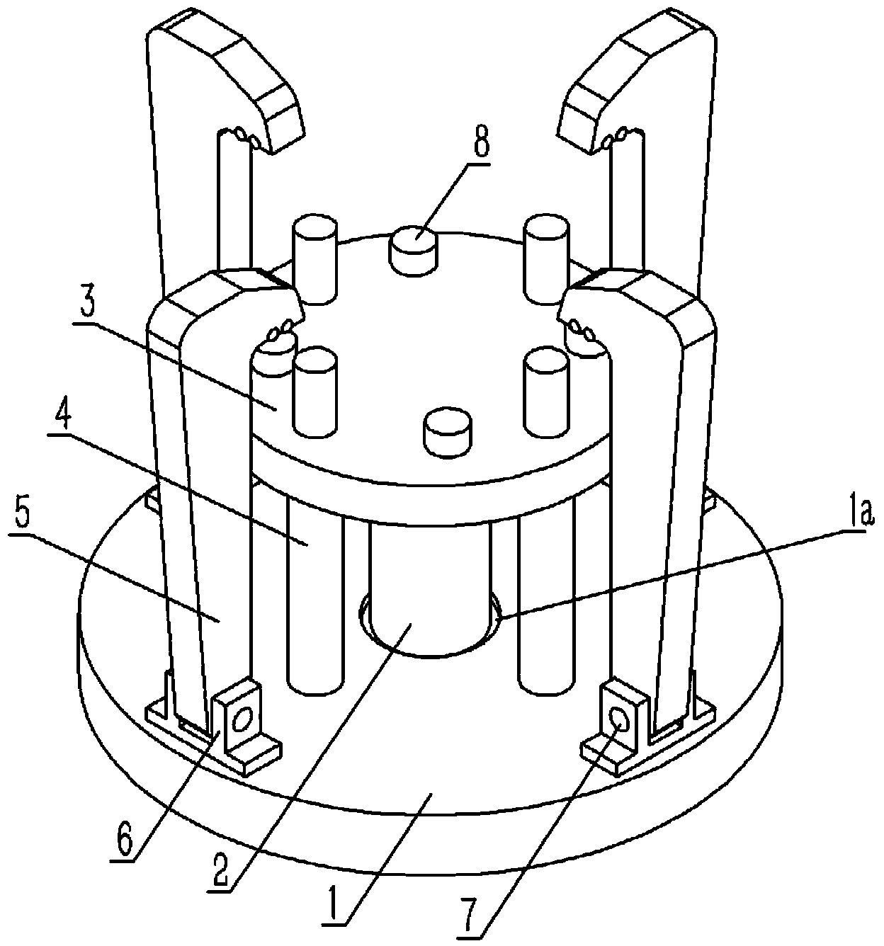
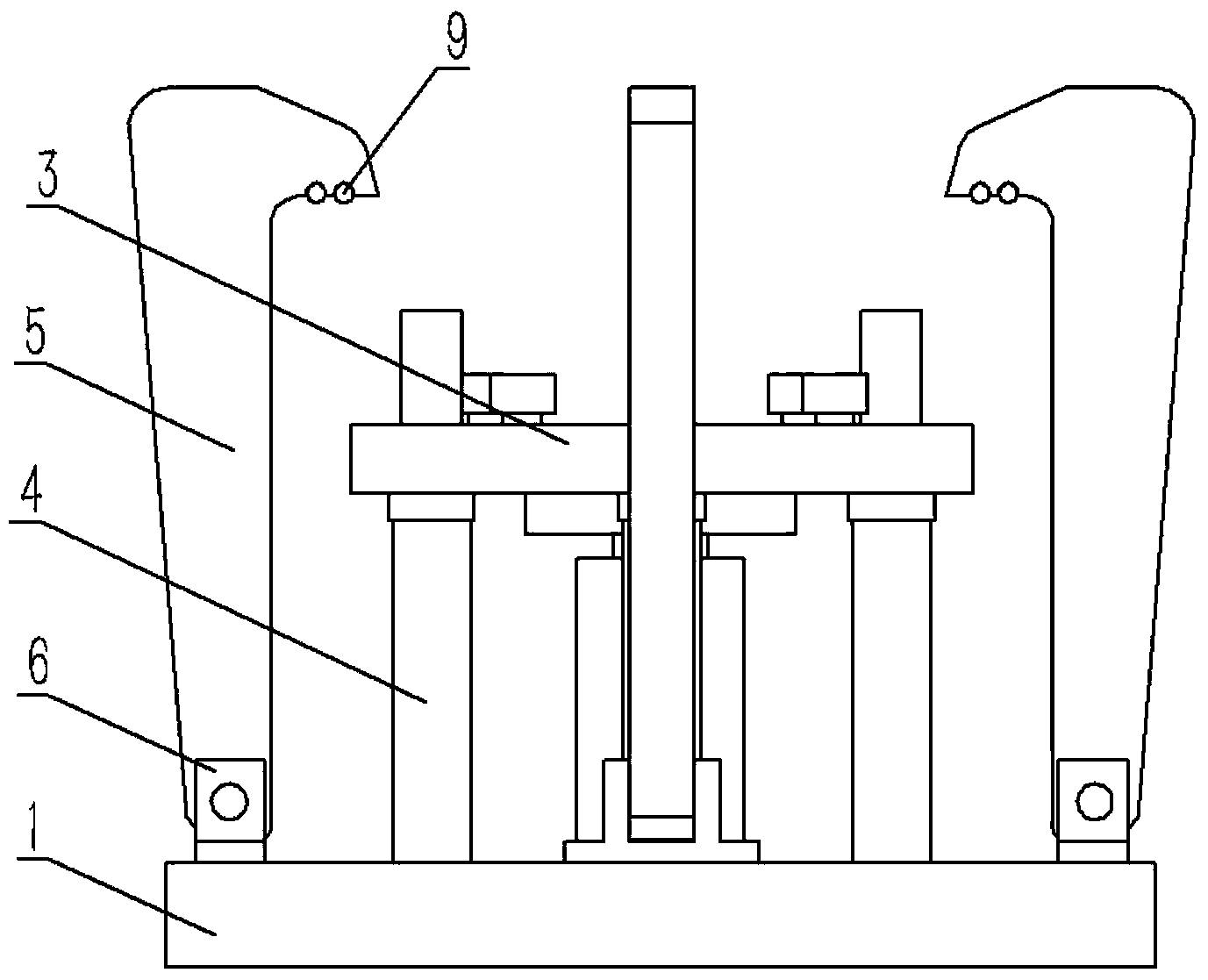
[0023] Example: see Figures 2 to 8 As shown, an automatic mold-drawing machine for a wheel casting mold includes a mold-pulling mechanism 10 and a mold mounting seat 20. The mold-pulling mechanism 10 includes a base 1, and the center of the base 1 is formed with a concave platform 1a, and the concave platform 1a of the base 1 An oil cylinder 2 is installed, and the piston rod of the oil cylinder 2 is fixed with an adjustment plate 11, the top plate 3 is pressed against the adjustment plate 11, and a number of adjustment bolts 8 are fixed on the upper end surface of the top plate 3, and the top plate 3 is plugged with A plurality of guide columns 4, the guide columns 4 are fixed on the base 1, and the outer side of the top plate 3 is provided with a plurality of drag hooks 5, and the drag hooks 5 are hinged on the base 1 through the hinge seat 6 and the hinge shaft 7;

[0024] The mold mounting seat 20 includes a bottom plate 21, a screw rod 22 is fixed on the bottom plate 21,...


PUM


Abstract

The invention discloses an automatic mold drawing machine for a wheel casting mold. The automatic mold drawing machine comprises a mold drawing mechanism and a mold mounting seat, wherein the mold drawing mechanism comprises a base; an oil cylinder is fixed at the center of the base; a top plate is fixed on a piston rod of the oil cylinder; a plurality of adjustment bolts are fixed on the upper end face of the top plate; a plurality of guide columns are inserted into the top plate and are fixed on the base; a plurality of pull hooks are arranged on the outer side of the top plate and are hinged to the base through hinge seats and hinge shafts; the die mounting seat comprises a base plate; a screw rod is fixed on the base plate; a plurality of guide sleeves are fixed on the base plate, and mandrils are inserted into the guide sleeves and correspond to the adjustment bolts on the drawing mechanism. The automatic mold drawing machine is designed for an upper casting mold of a wheel hub, so that manual demolding by a worker is replaced, and the problems of mandril locking and trouble in detaching are solved; therefore, the demolding speed is increased, injury to the mold is reduced, the labor intensity of the worker is alleviated, and the production efficiency is improved.

Description

Technical field: [0001] The invention relates to the technical field of auxiliary devices for casting aluminum equipment, and more specifically relates to an automatic mold lifting machine for wheel casting moulds. Background technique: [0002] At present, the wheel hub is generally formed by casting, and after the casting mold completes a production cycle, it needs to be fully maintained and repaired. It is necessary to disassemble the screw, top and bottom plates of the upper mold and other important links. The mold installation of the existing upper mold Seat such as figure 1 As shown, it is inserted into the screw rod 21 of the mold mounting seat, but due to the influence of high temperature and high pressure, the ejector pin is generally stuck, and the disassembly of the mold requires all the screws and ejector pins to be separated, or the mold must be manually clamped with an iron bar. The top plate needs to be knocked continuously to complete the disassembly, and th...

Claims


Application Information

Patent Timeline
IPC IPC(8): B22C19/06
CPCB22C19/06
Inventor 刘方宝陈振兴袁春章孟军毛秋仙
Owner ZHEJIANG WANFENG AUTO WHEEL
Learn More