
A liquid crystal based monocular compound eye integrated imaging detection chip

An imaging and liquid crystal technology, applied in the field of imaging detection, can solve the problems of poor environment and target adaptability, slow response, large inertia, etc., and achieve high structure and performance stability, as well as control accuracy, high spatial resolution and clarity, The effect of high measurement accuracy

Active Publication Date: 2017-06-27
HUAZHONG UNIV OF SCI & TECH
View PDF6 Cites 0 Cited by
  • Summary
  • Abstract
  • Description
  • Claims
  • Application Information

AI Technical Summary

Problems solved by technology

[0003] The method developed so far to construct a compound eye imaging detection framework by coupling a specific shape of refractive or diffractive microlenses with a photosensitive array has shown several defects, such as: (1) the arraying of a specific surface profile The microlens only has fixed optical performance, no ability to adjust the focus, adjust the point spread function, and change the field of view, and has poor adaptability to the environment and the target; (2) Each unit imaging microlens in the conventional microlens array can only match limited Large-scale sub-photosensitive arrays have low spatial resolution, image clarity and contrast, weak detail reproduction capabilities, serious lack of image layering, and poor completeness of target images; , to invert the conventional high spatial resolution and large-scale clear image of the target; (4) to achieve imaging focus or focusing needs to be performed through mechanical movement between multiple sets of converging or diverging microlens arrays arranged in cascade, slow response and state transition It takes a long time and has a large inertia, and it needs to be matched with a complex and precise auxiliary drive control device. Due to the intrinsic continuity of the motion posture, it is impossible to perform arbitrary optical state cut-in or jump, and the optical transformation capability is limited; Bionic compound eye structure coupled with photosensitive array chip

Method used


Image

  • A liquid crystal based monocular compound eye integrated imaging detection chip
  • A liquid crystal based monocular compound eye integrated imaging detection chip
  • A liquid crystal based monocular compound eye integrated imaging detection chip

Examples


Embodiment Construction

[0023] In order to make the object, technical solution and advantages of the present invention clearer, the present invention will be further described in detail below in conjunction with the accompanying drawings and embodiments. It should be understood that the specific embodiments described here are only used to explain the present invention, not to limit the present invention. In addition, the technical features involved in the various embodiments of the present invention described below can be combined with each other as long as they do not constitute a conflict with each other.

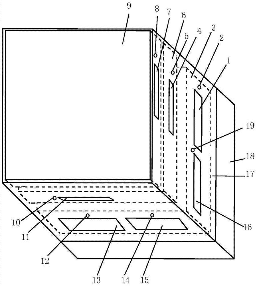
[0024] Such as figure 1 As shown, the liquid crystal-based single-eye and compound-eye integrated imaging detection chip of the present invention includes a ceramic housing 17 , a metal support and heat dissipation plate 18 , a single-eye and compound-eye integrated imaging detection structure, and a power port 15 .

[0025] The power port 15 is provided on the bottom surface of the ceramic she...


PUM


Abstract

The invention discloses a liquid crystal-based monocular compound eye integrated imaging detection chip, which includes a ceramic shell, a metal support and a heat dissipation plate, and a monocular compound eye integrated imaging detection structure. The rear part of the ceramic shell is fixed on the top of the metal support and heat dissipation plate. The compound eye integrated imaging detection structure is set in the ceramic shell, and includes the drive control and image preprocessing module arranged in coaxial order, the area array visible light detector, the area array electronically controlled liquid crystal imaging microlens, and the area array electronically controlled liquid crystal imaging microlens It is used to receive visible light from the top opening of the ceramic shell and focus the visible light to the area array visible light detector. The drive control and image preprocessing module receives the external working signal through the communication and control signal output port, and generates the driving signal according to the working signal. Signal. The liquid crystal-based single-eye compound-eye integrated imaging detection chip of the invention has the characteristics of compact structure, convenient use, easy coupling with conventional imaging optical systems, good adaptability to targets and environments, and the like.

Description

technical field [0001] The invention belongs to the technical field of imaging detection, and more specifically relates to a liquid crystal-based monocular compound eye integrated imaging detection chip. Background technique [0002] The compound eyes of insects such as flies, dragonflies and bees have multiple parallel imaging detection and the ability to perceive and identify moving targets. With imaging-based optical properties such as focal length, focal depth, focal spot position and size, clear aperture and point spread function, etc., it has a good adaptability to the environment and the target. So far, a variety of high-performance imaging detection devices have been developed by imitating insect compound eyes, such as typical co-located compound eye cameras, compound eye imaging detection architectures based on CCD, CMOS or FPAs, micro-self-focusing crystal cone bionic compound eyes, and multi-eye parallel-based Miniaturized wide field of view and large depth of fi...

Claims


Application Information

Patent Timeline
Patent Type & Authority Patents(China)
IPC IPC(8): H04N5/225H04N5/232
Inventor 张新宇雷宇罗俊佟庆桑红石张天序谢长生
Owner HUAZHONG UNIV OF SCI & TECH
Learn More