Workpiece laser measuring machine

A technology of laser measurement and measurement mechanism, applied in measurement devices, optical devices, instruments, etc., can solve the problems of easy fatigue, occupation of large workers, unreasonable design, etc., to ensure repeatability, continuity and efficiency. Effect

Inactive Publication Date: 2015-02-18
米亚精密金属科技(东莞)有限公司
View PDF7 Cites 10 Cited by
  • Summary
  • Abstract
  • Description
  • Claims
  • Application Information

AI Technical Summary

Problems solved by technology

The traditional measurement method is: use a measuring table to measure metal parts one by one, and often a workpiece needs to measure multiple points. In this way, it not only takes a lot of workers, but also takes a lot of time. Obviously , when workers repeat the same action from morning to night, they are prone to fatigue, making it difficult to guarantee the quality of measurement
In other words, the traditional method of measurement is not only time-consuming and laborious, but also difficult to guarantee the quality of the measurement
[0003] However, with the development of mechanical technology, the number of automated measuring equipment is also emerging, but due to the limitations of automation technology and unreasonable design, fully automated operations have not been well realized.
[0004] Moreover, some hardware parts require high-precision dimensions or data, which can only be met by equipment with high-precision measurement levels, but the measurement accuracy of current automation equipment is generally low

Method used


Image

  • Workpiece laser measuring machine
  • Workpiece laser measuring machine
  • Workpiece laser measuring machine

Examples


Embodiment Construction

[0025] The present invention will be described in further detail below in conjunction with the accompanying drawings.

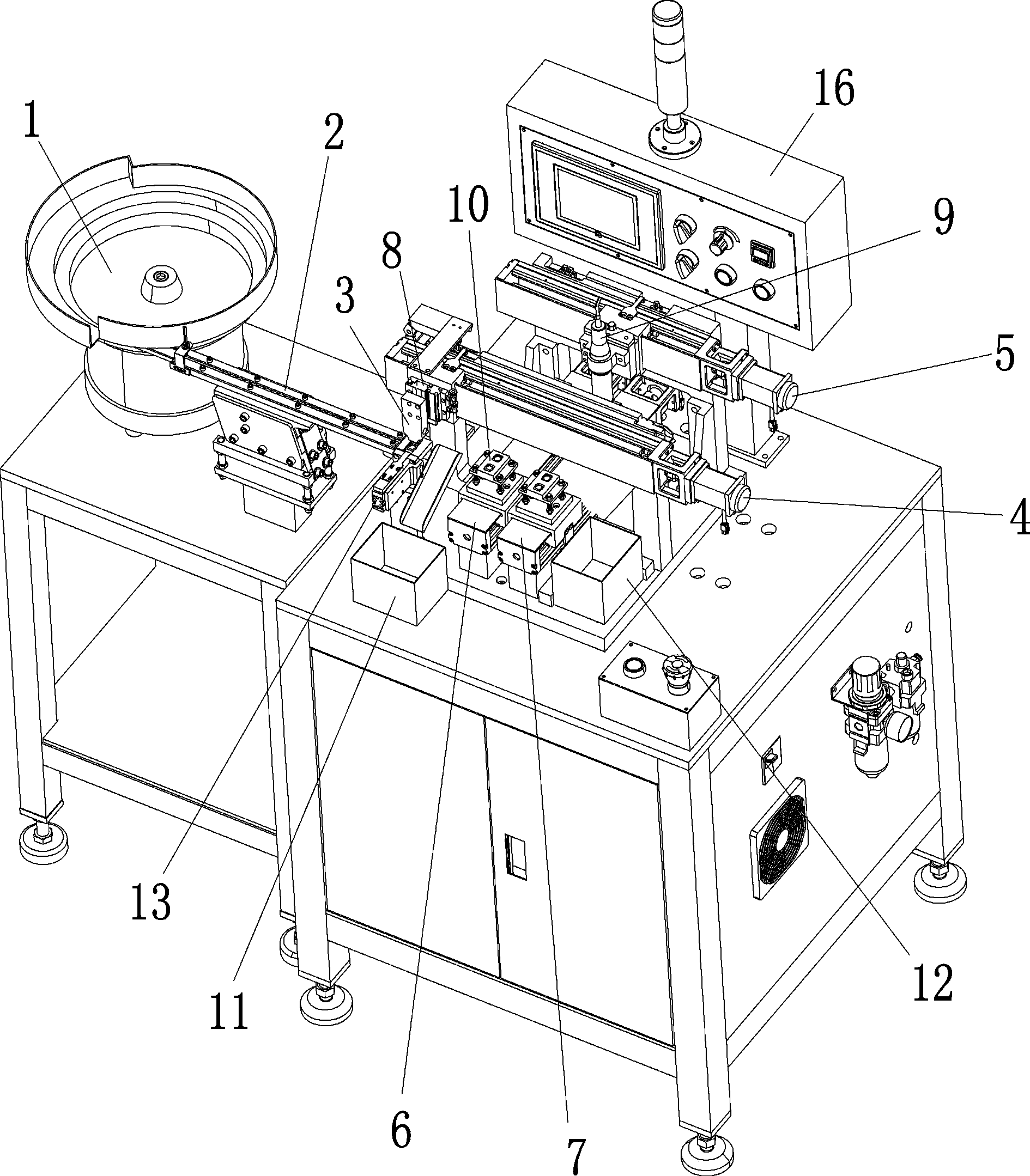
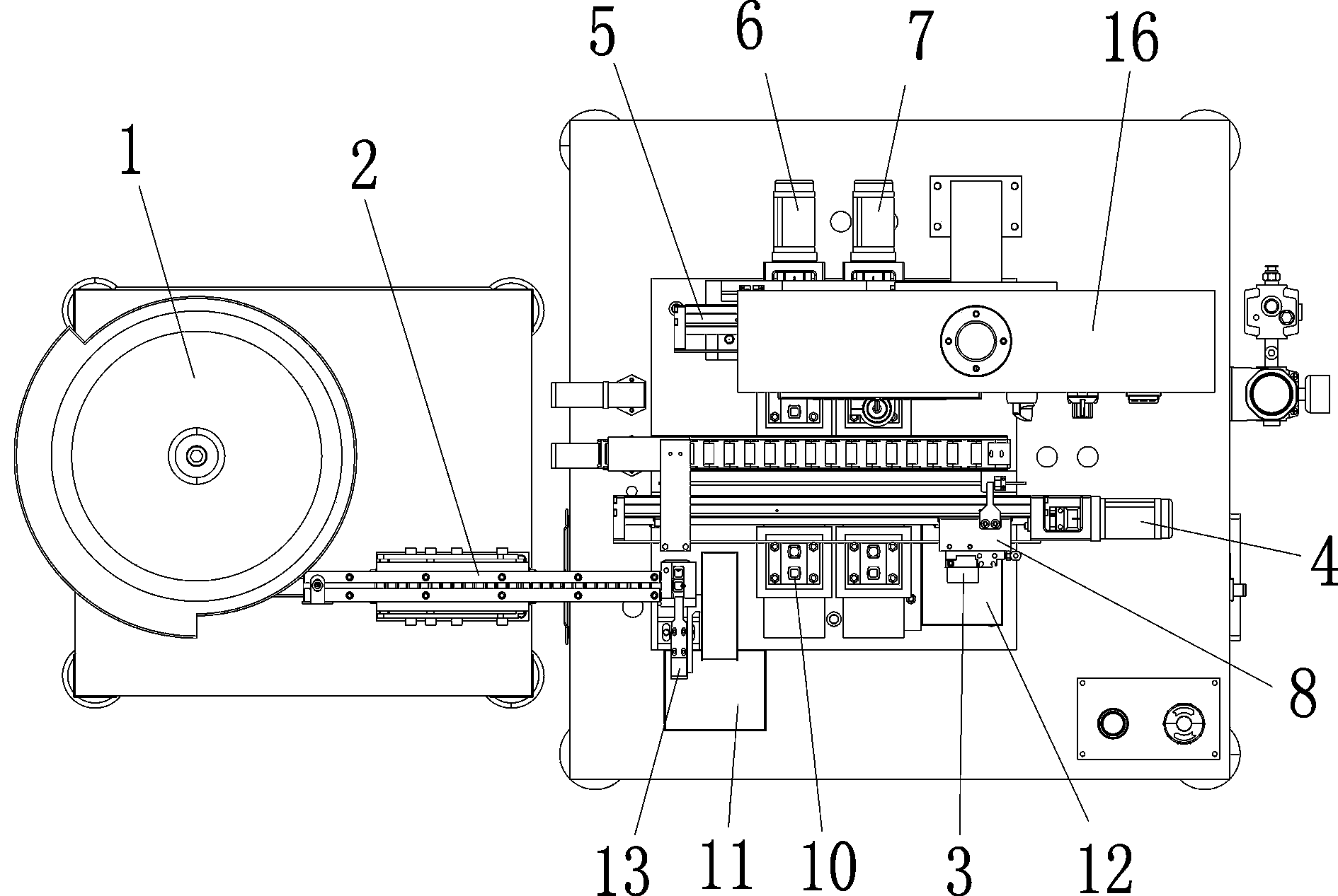
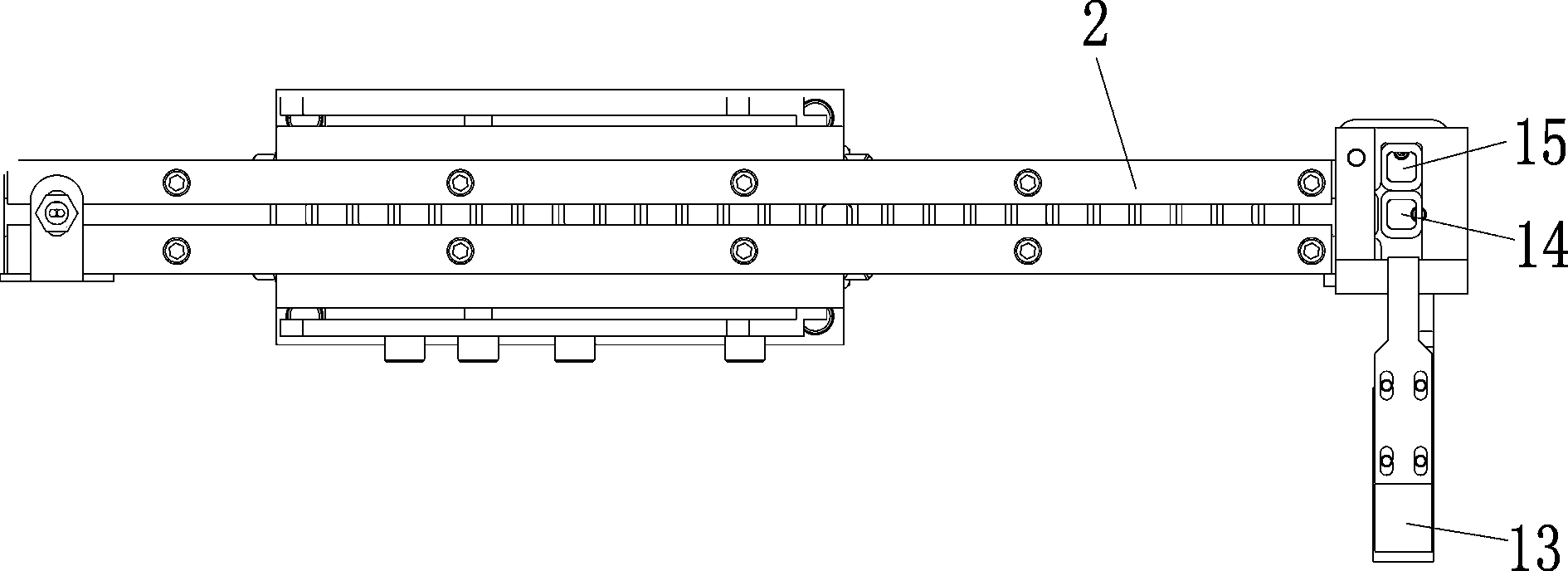
[0026] Such as figure 1 , 2 , Shown in 3, a kind of workpiece laser measuring machine comprises a feeding mechanism, a feeding mechanism and a measuring mechanism; the feeding mechanism is used for feeding, and includes a disc vibrating device 1 and a linear vibrating device 2, and the workpiece is obtained from the described The disc vibrating device 1 is arranged in the linear vibrating device 2; the transport mechanism is used for taking, loading and unloading, including a moving device and a manipulator 3; the measuring mechanism is used for data detection of workpieces , comprising a laser measuring head 9; the manipulator 3 and the laser measuring head 9 are installed in the moving device, and the moving device controls the simultaneous operation of the manipulator 3 and the laser measuring head 9; the manipulator 3 will The workpiece is transported t...


PUM


Abstract

The invention discloses a workpiece laser measuring machine which comprises a workpiece supply mechanism, a workpiece conveying mechanism and a measuring mechanism. The workpiece supply mechanism comprises a disc vibrating device and a linear vibrating device. Workpieces are arranged in the disc vibrating device and enter the linear vibrating device. The workpiece conveying mechanism is used for taking, loading and discharging the workpieces and comprises a moving device and a mechanical arm. The measuring mechanism is used for performing data detection on the workpieces and comprises a laser measuring head. The mechanical arm and the laser measuring head are mounted in the moving device. The moving device controls the mechanical arm and the laser measuring head to operate at the same time. The mechanical arm moves the workpieces from the workpiece supply mechanism to corresponding stations, and moves the workpieces to corresponding collecting stations after the laser measuring head detects the workpieces. The workpiece laser measuring machine has the advantages that workpiece supplying, taking, loading, discharging and measuring can be performed synchronously in a full-automatic manner, measuring efficiency is guaranteed, and cost is saved.

Description

technical field [0001] The invention relates to the technical field of automatic measuring equipment, in particular to a workpiece laser measuring machine. Background technique [0002] At present, in the mobile phone manufacturing industry, there are a large number of measurements of small metal parts. The traditional measurement method is to use a measuring table to measure metal parts one by one, and often a workpiece needs to be measured at multiple points. In this way, it not only takes a lot of workers, but also takes a lot of time. Obviously , When workers repeat the same action from morning to night, they are prone to fatigue, making it difficult to guarantee the quality of measurement. In other words, the traditional method of measurement is not only time-consuming and laborious, but also difficult to guarantee the quality of the measurement. [0003] However, with the development of mechanical technology, the number of automated measuring equipment is also emergi...

Claims


Application Information

Patent Timeline
IPC IPC(8): G01B11/00
Inventor 钟剪
Owner 米亚精密金属科技(东莞)有限公司
Why Eureka
Try Eureka