Energy-saving combined wind power/water power generation device and system

A technology of hydroelectric power generation device and power generation device, which is applied in the direction of hydropower generation, wind motor combination, wind power engine, etc. It can solve the problems of low utilization rate of wind power or water power, inability to directly connect to the power grid, unstable generator speed, etc. Stabilize, make full use of natural energy, and increase the effect of windward/water area

Active Publication Date: 2015-02-18
王振林
View PDF4 Cites 3 Cited by
  • Summary
  • Abstract
  • Description
  • Claims
  • Application Information

AI Technical Summary

Problems solved by technology

[0002] The current wind power or hydropower generation is a power generation system composed of a wind wheel or a water turbine and a generator alone. Because the wind wheel or water turbine is affected by the wind or water flow, the speed of the generator is unstable and the voltage is unstable, requiring an electric energy storage device (battery) ), can be connected to the grid through conversion, but cannot be directly connected to the grid
In addition, because the wind or water turbines are installed in a single layer, the utilization rate of wind or water power is low, usually only 30-50%. In the case of sudden increase in water or wind power, the power generation system will be damaged due to the high speed.

Method used


Image

  • Energy-saving combined wind power/water power generation device and system
  • Energy-saving combined wind power/water power generation device and system
  • Energy-saving combined wind power/water power generation device and system

Examples


Embodiment Construction

[0040] The present invention will be further described below in conjunction with the accompanying drawings and embodiments.

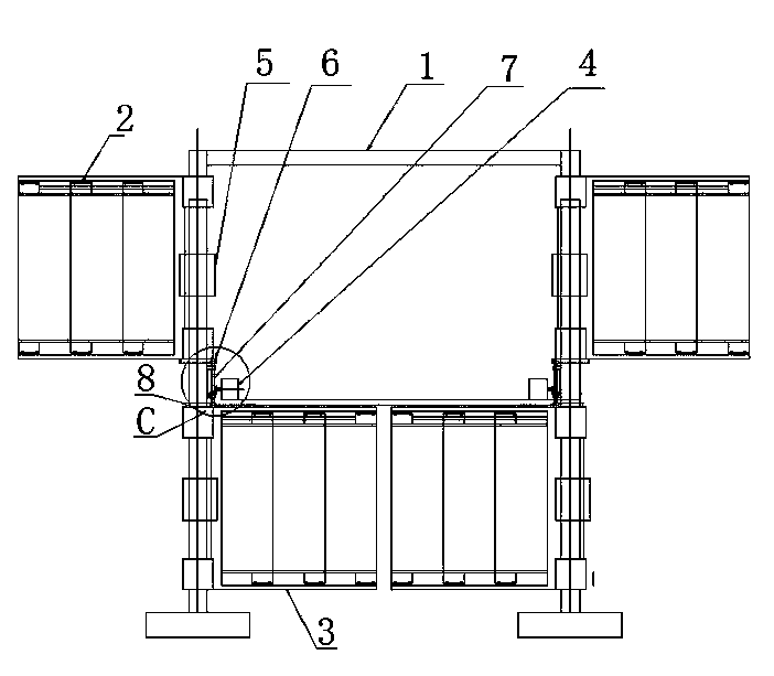
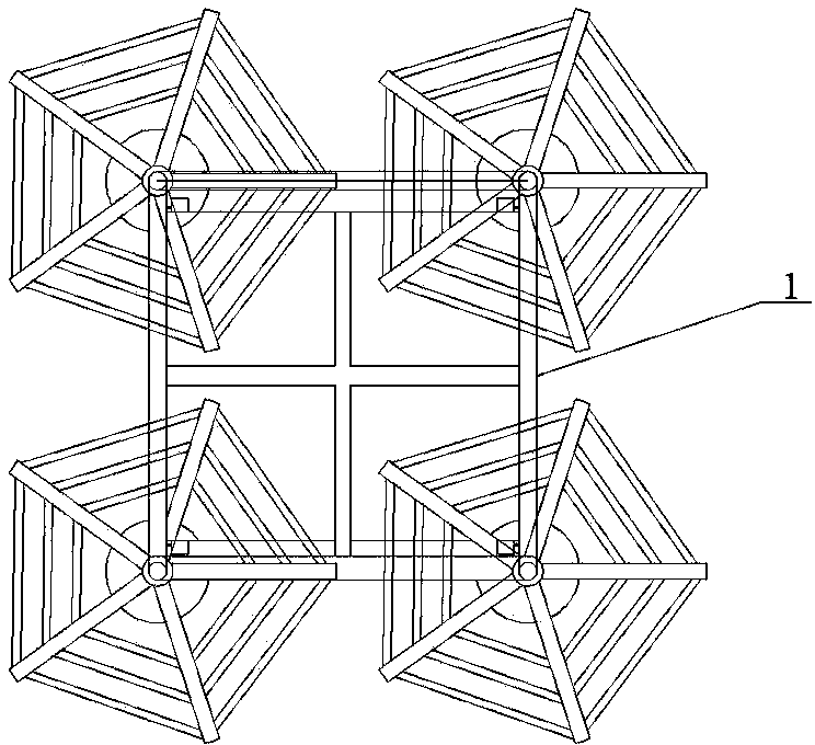
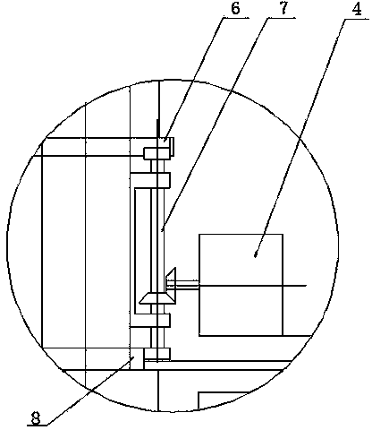
[0041] Refer to attached Figure 1-9 Shown: energy-saving wind / hydraulic combined power generation device, including a support frame 1, there are at least four power generation units on the support frame, the structure of the power generation unit consists of an upper blade wheel 2, a lower blade wheel 3, an overflow variable speed power generation device 4 components, the rotation directions of the upper blade wheel 2 and the lower blade wheel 3 are opposite, the structures of the upper blade wheel and the lower blade wheel are symmetrical, and the upper blade wheel 2 and the lower blade wheel 3 are coaxially installed on the column of the support frame;

[0042]The upper blade wheel includes a central support column 201, 3-6 blade support frames (5 in this embodiment) that are uniformly distributed along the center support column, and the blade suppor...


PUM


Abstract

The invention discloses an energy-saving combined wind power / water power generation device and an energy-saving combined wind power / water power generation system. Wind power generation or water power generation or combined power generation can be performed. According to the energy-saving combined wind power / water power generation device, at least four power generation units are arranged on a supporting frame; all corresponding left and right blade wheels and corresponding upper and lower blade wheels rotate in the opposite direction, so that the utilization rate of windward / upstream area is maximum; the upper and lower blade wheels of each power generation unit pass through a same-direction output conversion device to an overflow speed-changing power generation device, an output shaft is driven by a multi-stage one-way clutch, and then a generator is driven. When wind speed / water speed is changed, the windward / upstream area is automatically decreased or increased by virtue of the overflow speed-changing power generation device and a counterweight device, and normal operation is guaranteed. The energy-saving combined wind power / water power generation system is formed by combining and superposing a plurality of wind power / water power generation devices in a vertical direction, a horizontal direction (S-shaped arrangement layout) or two directions. A sand storm can be resisted in a wind area, the device and the system can be used in a river and an ocean in a mixed way, and land resources are saved.

Description

technical field [0001] The invention relates to a power generation device utilizing natural force, in particular to an energy-saving wind power / hydraulic combined power generation device and a wind power / hydraulic power generation system. Background technique [0002] The current wind power or hydropower generation is a power generation system composed of a wind wheel or a water turbine and a generator alone. Because the wind wheel or water turbine is affected by the wind or water flow, the speed of the generator is unstable and the voltage is unstable, requiring an electric energy storage device (battery) ), can only be connected to the grid through conversion, but cannot be directly connected to the grid. In addition, because the wind or water turbines are installed in a single layer, the utilization rate of wind or water power is low, usually only 30-50%. In the case of sudden increase in water or wind power, the power generation system will be damaged due to the high sp...

Claims


Application Information

Patent Timeline
Patent Type & Authority Applications(China)
IPC IPC(8): F03D9/00F03D3/02F03D3/06F03B13/00F03B3/14
CPCF03B3/14F03B13/00F03D3/02F03D9/008F03D9/25F05B2240/21F05B2240/30Y02E10/20Y02E10/74
Inventor 王振林
Owner 王振林
Why Eureka
Try Eureka