
Automatic liquid following infusion head for soft bag infusion

A soft bag infusion and automatic technology, applied in the direction of subcutaneous injection equipment, etc., can solve problems such as mixing, inability to use, medical accidents, etc., and achieve the effects of low cost, simple structure, and reduced labor intensity

Inactive Publication Date: 2015-02-18
刘玮
View PDF7 Cites 2 Cited by
  • Summary
  • Abstract
  • Description
  • Claims
  • Application Information

AI Technical Summary

Problems solved by technology

[0003] Must be used in hard plastic or glass bottle dispensing containers, not in soft bag dispensing containers
This is because soft containers can be used for infusion without air intake. If this solution is used for continuous infusion of soft bottle groups, that is, when the second or subsequent liquid bottles are soft containers, it may cause the second or subsequent liquids to be infused. Early output and mixed with the first bottle of liquid, causing medical accidents
Therefore, the infusion group used in this program can only be the first bottle as an infusion bag at most, because the first bottle can be infused regardless of whether it is air-filled or not, and the automatic bottle-changing function starts from the second bottle, and only It is used for hard bottles to achieve the purpose of continuous infusion

Method used


Image

  • Automatic liquid following infusion head for soft bag infusion
  • Automatic liquid following infusion head for soft bag infusion
  • Automatic liquid following infusion head for soft bag infusion

Examples


Embodiment Construction

[0013] In order to facilitate the understanding of the present invention, the present invention will be described more fully below with reference to the associated drawings. A preferred embodiment of the invention is shown in the drawings. However, the present invention can be embodied in many different forms and is not limited to the embodiments described herein. Rather, these embodiments are provided so that the disclosure of the present invention will be thorough and complete.

[0014] It should be noted that when an element is considered to be "disposed" on another element, it may be directly mounted on the other element or there may be an intervening element at the same time.

[0015] Unless otherwise defined, all technical and scientific terms used herein have the same meaning as commonly understood by one of ordinary skill in the technical field of the invention. The terms used in the description are only for describing specific implementation purposes, and are not in...


PUM


Abstract

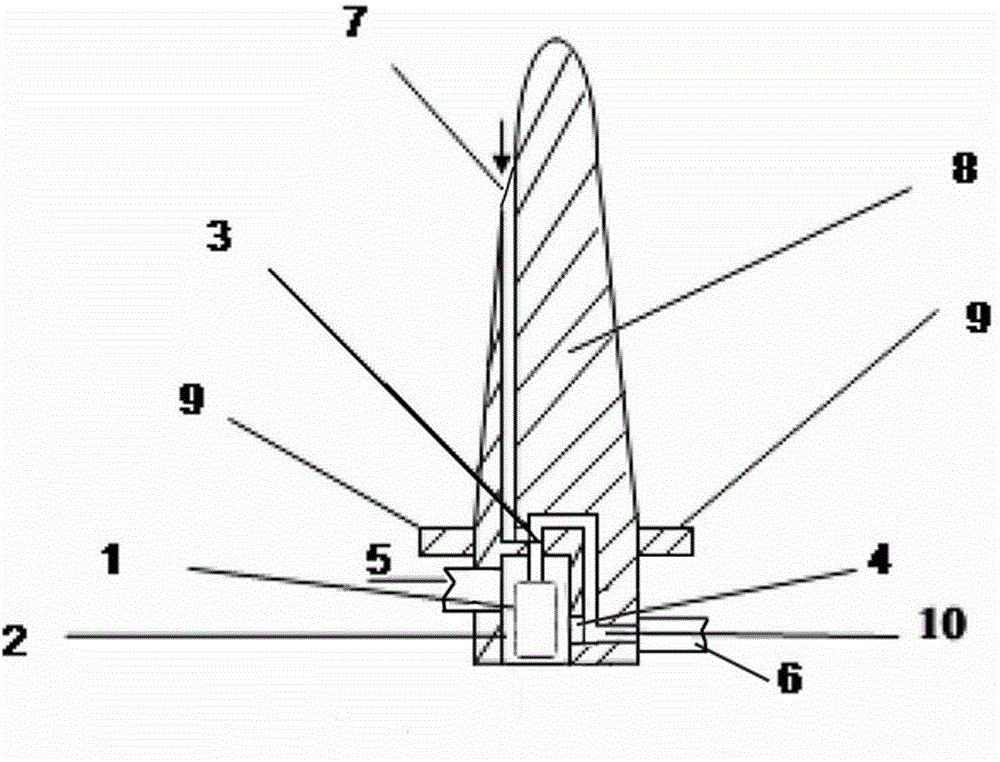
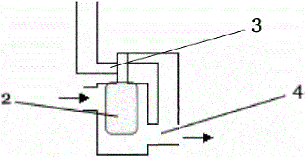
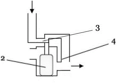
The invention relates to an automatic liquid following infusion head for soft bag infusion. A liquid inlet channel, a liquid outlet channel and a floating valve are arranged in an infusion head body of the automatic liquid following infusion head, wherein the floating valve is arranged at the bottom end of the infusion head body and consists of a floating valve chamber, a floating ball and a valve; the floating ball is arranged in the floating valve chamber and floats up and down; the valve is connected with the floating ball; one side of the floating valve chamber is communicated with the liquid inlet pipe; a channel is arranged on the other side of the floating valve chamber and is communicated with the liquid outlet channel; an opening and a channel for a liquid feeding pipe are respectively arranged on two sides of the floating valve chamber; the valve is arranged between the liquid inlet channel and the liquid outlet channel; the liquid inlet channel and the liquid outlet channel are blocked by the valve through upward floating of the floating ball; the liquid inlet channel and the liquid outlet channel are communicated by the valve through sinking of the floating ball; the liquid outlet channel and the channel are respectively communicated with the liquid outlet pipe. According to the automatic liquid following infusion head disclosed by the invention, the infusion path of a soft bag container is controlled by closing or opening the floating valve, and automatic change of bottles is realized. The automatic liquid following infusion head has the advantages of simple structure, low cost and easiness for popularization in a wide range; the labor intensity of medical workers is reduced.

Description

technical field [0001] The invention relates to the technology of automatic bag changing for medical infusion, and refers to an automatic liquid-successor infusion head specially used for soft bag infusion, which uses physical principles to automatically control the successive input of liquid in an infusion group. Background technique [0002] I originally applied for an invention patent (patent number: ZL201210408974.4) on the use of physical principles to control the automatic bottle change of infusion, which realizes automatic bottle change by controlling the intake of multiple bottles of liquid in sequence. There are many limitations in actual use, such as: [0003] Must be used in hard plastic or glass bottle dispensing containers, not in soft bag dispensing containers. This is because soft containers can be used for infusion without air intake. If this solution is used for continuous infusion of soft bottle groups, that is, when the second or subsequent liquid bottles...

Claims


Application Information

Patent Timeline
IPC IPC(8): A61M5/175
CPCA61M5/16827
Inventor 沈颖惠刘玮刘诗舫沈博宇刘绍勇
Owner 刘玮
Learn More