A kind of conveying device and conveying chain group

A transmission device and transmission chain technology, applied in the direction of conveyors, conveyor objects, transportation and packaging, etc., can solve problems such as tilting and scattering, lack of transmission devices, and unsolvable problems, and achieve adjustable and accurate adjustment of the limit distance High degree of anti-rolling effect

Active Publication Date: 2017-01-18
GUANGDONG LONGXING PACKAGING IND
View PDF7 Cites 0 Cited by
  • Summary
  • Abstract
  • Description
  • Claims
  • Application Information

AI Technical Summary

Problems solved by technology

However, there is a lack of special conveying devices for the transfer and transportation of the substrates of the flat printing and stamping equipment stacked in strips, especially the entire flat printing substrates with irregular shapes are prone to be tilted and scattered during the transmission process, usually not Easy to apply automatic transfer
At present, there is still no automatic transfer technology that can solve the problem of flat stamping
[0003] Moreover, the existing conveying device cannot adjust the limit distance for carrying the substrate and restricting its rolling according to the difference of the substrate being transported each time.
Chinese utility model patent (notification number: CN912246U) discloses "a conveyor belt". The technical problem solved by this technology is to limit the transmission of electric wires, and it cannot solve the problem that the stacked strips of covers and other printing materials are easy to fall during storage and transmission. Scattered, multi-angle and multi-position high-speed transmission problems, and the function of adjusting the limit spacing cannot be realized

Method used


Image

  • A kind of conveying device and conveying chain group
  • A kind of conveying device and conveying chain group
  • A kind of conveying device and conveying chain group

Examples


Embodiment 1

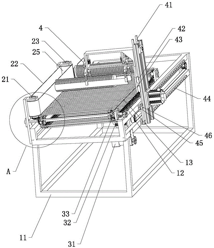
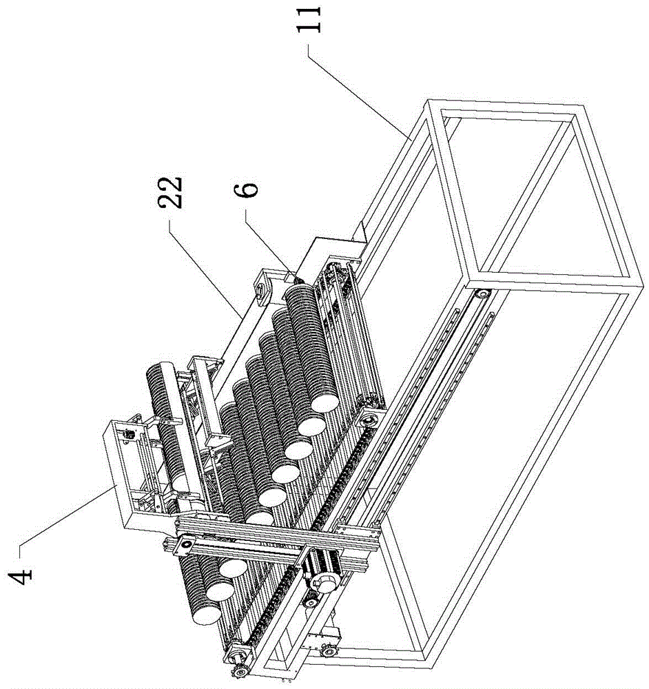
[0050] like Figure 1 to Figure 5As shown, a transmission device in this embodiment includes a transmission support frame 11, a driving device, a transmission chain set, an abutting device and a bevel gear set. The transmission chain group includes two transmission chains 12 and a plurality of limit rods 13, the transmission chain group includes two transmission chains 12 and a plurality of limit rods 13, and each transmission chain 12 includes a plurality of chain links, and the chain links One side plate is set as a right-angle plate 121, and the right-angle plates 121 of two adjacent chain links of the same conveyor chain 12 are respectively located on both sides of the conveyor chain 12, and the right-angle plate 121 is provided with two rows of fixing holes 122, and two rows of fixing holes 122 Specifically, the first row and the second row, the centers of the fixing holes in the second row are located on the center bisector of the two adjacent fixing holes in the first r...

Embodiment 2

[0056] The main technical solution of this embodiment is basically the same as that of Embodiment 1, and the features not explained in this embodiment are explained in Embodiment 1, and will not be repeated here. On the basis of Embodiment 1, this embodiment also includes a plurality of adjustable fittings 14. The adjustable fittings 14 are provided with a plurality of adjustment holes 141 and fitting fixing holes 142122 corresponding to the fixing holes 122 of the rectangular plate 121. The accessory 14 is installed in the fixing hole 122 of the direct plate through the accessory fixing hole 142122 through a pin or a bolt, and the limit rod 13 is detachably fixed to the adjustable accessory through a pin or a bolt to connect the through hole 131 and the accessory fixing hole 142122 14.

Embodiment 3

[0058] The main technical solutions of this embodiment are basically the same as those of Embodiment 2, and the features not explained in this embodiment are explained in Embodiment 2, and will not be repeated here. In this embodiment, a plurality of adjustment holes 141 are arranged in two rows, specifically a first row and a second row, and the center of the adjustment holes 141 in the second row is located at the center bisector of two adjacent adjustment holes 141 in the first row.


PUM


Abstract

A conveyor comprises a conveying support frame and a driving device and further comprises a conveyor chain group, a leaning device and a bevel gear group, wherein the conveyor chain group is arranged on the conveying support frame, and the leaning device is used for allowing printing substrates such as lids, plates and dishes which are stacked into a strip to lean so as to prevent the printing substrates from collapsing; limiting grooves are formed among a plurality of limiting rods, can effectively prevent the printing substrates or the lids stacked into the strip from rolling, slanting or scattering in the flatwise conveying process and are matched with the leaning device. In the conveyor chain group, the limiting rods are detachably arranged on right-angle plates, the printing substrates stacked into the strip are limited in the limiting grooves formed between the two adjacent limit rods and are effectively prevented from rolling, slanting and scattering, and limiting spaces between the limiting rods are regulated according to the width of the printing substrates stacked into the strip. The precision is high, and the adjustable limiting space is realized.

Description

technical field [0001] The invention relates to the technical field of conveying and transporting, in particular to a conveying device and a conveying chain group for plane seals. Background technique [0002] At present, there are various types of conveyor chains, conveyor belts, and conveyor devices at home and abroad, and there are corresponding conveyor components and devices for different products in different industries. However, there is a lack of special conveying devices for the transfer and transportation of the substrates of the flat printing and stamping equipment stacked in strips, especially the entire flat printing substrates with irregular shapes are prone to be tilted and scattered during the transmission process, usually not Easy to apply automatic transfer. At present, there is still no automatic transfer technology that can solve the problem of flat stamping. [0003] Moreover, the existing conveying device cannot adjust the limit distance for carrying ...

Claims


Application Information

Patent Timeline
Patent Type & Authority Patents(China)
IPC IPC(8): B65G21/20B65G17/46B65G47/90B65G17/12
CPCB65G17/12B65G17/46B65G21/20B65G47/90
Inventor 王昌佑许逸生
Owner GUANGDONG LONGXING PACKAGING IND
Why Eureka
Try Eureka