
Wireless charging circuit and control method thereof

A wireless charging and circuit technology, applied in battery circuit devices, circuit devices, control/regulation systems, etc., can solve the problem of severe fluctuations in transmission power and transmission distance, and achieve the effect of easy hardware and simple control methods

Active Publication Date: 2015-02-04
HUAZHONG UNIV OF SCI & TECH
View PDF6 Cites 38 Cited by
  • Summary
  • Abstract
  • Description
  • Claims
  • Application Information

AI Technical Summary

Problems solved by technology

[0004] Aiming at the defects of the prior art, the object of the present invention is to provide a wireless charging circuit and its control method, aiming at solving the problem that the transmission power in the existing wireless power transmission circuit easily fluctuates violently with the change of the transmission distance (or offset distance)

Method used


Image

  • Wireless charging circuit and control method thereof
  • Wireless charging circuit and control method thereof
  • Wireless charging circuit and control method thereof

Examples


Embodiment approach

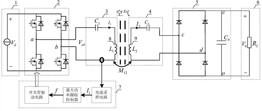
[0049] The wireless charging circuit and its control method proposed by the present invention are based on the wireless charging circuit such as figure 1 shown. The circuit mainly includes a DC power supply 1, a high-frequency inverter unit 2, a primary side compensation unit 3, a power transmitting coil 8 and a power receiving coil 9, a secondary side compensation unit 4, an uncontrolled rectification unit 5, a load 6 and a power control unit 7 .

[0050] Wherein, the function of the DC power supply 1 is to provide a stable DC voltage V for the high-frequency inverter unit 2 d ; The high-frequency inverter unit 2 inverts direct current into a high-frequency voltage square wave, and its structure is a full-bridge inverter circuit composed of four switching tubes, and the output terminals a and b are connected to the primary side compensation unit 3; The primary side compensation unit 3 consists of a resonant capacitor C 1 Composed in series with the power transmitting coil ...


PUM


Abstract

The invention discloses a wireless charging circuit and a control method thereof. The circuit is characterized in that the magnetic coupling type wireless power transmission technology is adopted. The circuit mainly comprises a DC power supply, a primary side high-frequency inverting unit, a primary side series-compensative unit, a power emitting coil, a power receiving coil, a secondary side series-compensative unit, an uncontrolled rectifying unit and a load and power controller unit. According to the wireless charging circuit and the control method, the primary side current is used as the feedback quantity, the maximum power tracking control method based on the variable step size perturbation and observation mode is adopted to automatically adjust the working frequency of the circuit, thus the circuit can work in a circuit frequency splitting point on real time, and as a result, the stable output of the transmission power can be realized; when the deviation distance of a power transceiving coil is within a certain transmission range, the load end of the wireless power transmission circuit can obtain the maximum stable power and is not influenced by the deviation position on the premise that the primary side and the secondary side do not communicate; the requirements on the real-time communication of the primary side and the secondary side are saved; the control method is simple and reliable; the stability of the transmission power can be effectively improved; the wireless charging circuit like an electric car or a mobile charging circuit and the like with requirement on a certain deviation distance apply.

Description

technical field [0001] The invention belongs to the technical field of wireless power transmission, and relates to a wireless charging circuit and a control method thereof. Background technique [0002] In recent years, wireless power transmission technology has achieved rapid development, especially the wireless power transmission technology of magnetic coupling. This method transmits energy through the magnetic field coupling of the power transceiver coil, and the primary and secondary sides are added to the compensation network to improve the transmission power and efficiency. Magnetic coupling wireless power transmission technology has been successfully applied in low-power portable electronic devices (such as mobile phones and notebooks) and wireless charging of electric vehicles. However, these application products require real-time two-way communication between the primary and secondary sides, and the transceiver coil must have a certain alignment operation to ensure...

Claims


Application Information

Patent Timeline
IPC IPC(8): H02J17/00H02M3/335H02J50/12
CPCH02J7/025H02M3/33507
Inventor 段善旭赵锦波丰昊蔡涛
Owner HUAZHONG UNIV OF SCI & TECH
Learn More