
Time domain and modulation domain parameter combined measuring method of triangular frequency-modulation pulse signals

A technology of pulse signal and triangular frequency modulation, which is applied in the radar field, can solve problems such as fuzzy time-frequency distribution, inaccurate measurement, and large amount of calculation, and achieve the effect of reduced calculation amount, good precision requirements, and small calculation amount

Active Publication Date: 2015-02-04
XIDIAN UNIV
View PDF3 Cites 8 Cited by
  • Summary
  • Abstract
  • Description
  • Claims
  • Application Information

AI Technical Summary

Problems solved by technology

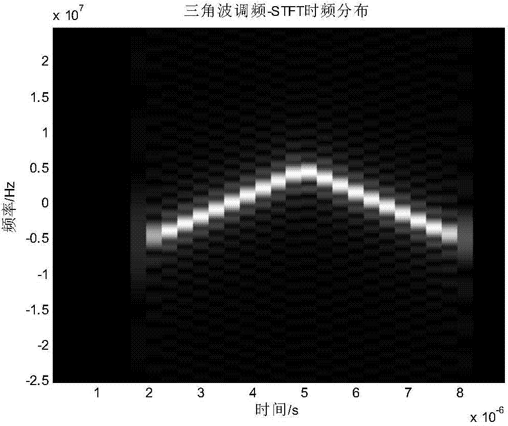
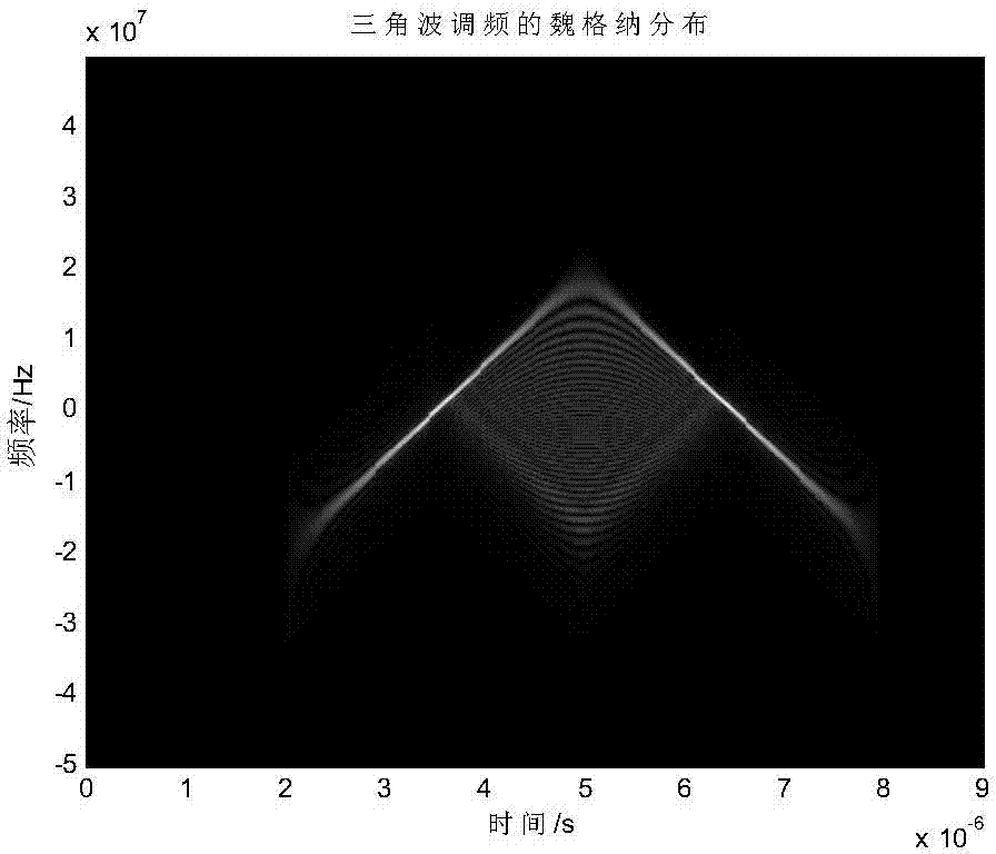
STFT has the problem of difficult selection of window length and window function. Due to the use of Fourier transform, the amount of calculation is large, and it is limited by the uncertainty criterion, which cannot solve the contradiction between time resolution and frequency resolution.
Although the Wigner-Vile distribution does not use a window function, there is no STFT problem, but there are "cross-term" interferences in the time-frequency distribution of multi-component signals (such as triangular FM signals), and the time-frequency distribution will become blurred. The frequency estimation Not allowed, and it uses integral calculation, which has a large amount of calculation

Method used


Image

  • Time domain and modulation domain parameter combined measuring method of triangular frequency-modulation pulse signals
  • Time domain and modulation domain parameter combined measuring method of triangular frequency-modulation pulse signals
  • Time domain and modulation domain parameter combined measuring method of triangular frequency-modulation pulse signals

Examples


Embodiment Construction

[0033] The present invention will be described in further detail below in conjunction with the accompanying drawings.

[0034] In modern radar electronic warfare, the time domain and modulation domain parameters of the radar echo carry a lot of useful information, but the parameters of the radar echo are unknown and cannot be directly obtained through the radar receiving antenna. For different types of radar signals, the parameter measurement methods are also different. The triangular FM pulse signal is a common transmission signal of radar. Measuring the parameters of the triangular FM pulse signal is one of the key points in the field of radar signal processing engineering. Due to the complex characteristics of the intra-pulse modulation, the triangular FM pulse signal makes parameter measurement extremely difficult, and the amount of calculation is huge, and the problem of inaccurate measurement often occurs. In order to accurately and quickly measure the time domain and mo...


PUM


Abstract

The invention discloses a time domain and modulation domain parameter combined measuring method of triangular frequency-modulation pulse signals and mainly solves the problems of low parameter accuracy and high operation load in measurement of the triangular frequency-modulation pulse signals in the prior art. The time domain and modulation domain parameter combined measuring method includes steps of 1, acquiring real and imaginary part discrete values of the triangular frequency-modulation pulse signals by a signal analyzer; 2, calculating signal envelopes of the triangular frequency-modulation pulse signals according to the discrete values; 3, estimating the approximate amplitude of the triangular frequency-modulation pulse signals by the signal envelopes; 4, setting a judgment threshold by the approximate amplitude and detecting the number of pulses; 5, calculating the pulse width of each pulse; 6, calculating various time domain parameters by the number of the pulse and the pulse widths; 7, calculating instant frequency of the triangular frequency-modulation pulse signals on the basis of the time domain parameters; 8, calculating various modulation domain parameters of the triangular frequency-modulation pulse signals by the instant frequency. The simulation results indicated that the time domain and modulation domain parameter combined measuring method is low in operation load and higher in accuracy under the condition of high signal to noise ratio as compared with existing methods.

Description

technical field [0001] The invention relates to the field of radar technology, in particular to a method for joint measurement of time domain modulation domain parameters of triangular frequency modulation pulse signals, which can be used in modern radar electronic warfare to measure key information of triangular frequency modulation radar signals. Background technique [0002] Triangular FM pulse signal is a kind of transmission signal often used in modern radar electronic warfare. It has the advantages of insensitivity to Doppler frequency shift and solving the contradiction between signal energy and distance resolution. Measuring the parameters of the triangular FM pulse signal is one of the key points in the field of radar signal processing engineering. Traditional measurement methods only target time domain or modulation domain, and do not combine time domain and modulation domain for parameter measurement. Moreover, time-frequency analysis is required to measure the m...

Claims


Application Information

Patent Timeline
Patent Type & Authority Applications(China)
IPC IPC(8): G01S7/41
CPCG01S7/411
Inventor 张林让赵健刘艺苗雪平雷宇
Owner XIDIAN UNIV
Learn More