Eureka AIR delivers breakthrough ideas for toughest innovation challenges, trusted by R&D personnel around the world.

Current transformer based on magnetically controlled grating light valve and method for detecting bus current

A technology of current transformer and grating light valve, which is used in the measurement of current/voltage, voltage/current isolation, instruments, etc., can solve the problems of high machining process requirements, difficult to improve accuracy, difficult to large-scale application, etc. Energy supply cost, lower insulation design cost, low cost effect

Active Publication Date: 2017-02-01
SOUTHEAST UNIV
View PDF5 Cites 0 Cited by
  • Summary
  • Abstract
  • Description
  • Claims
  • Application Information

AI Technical Summary

Problems solved by technology

In 1996, the University of Calgary in Canada proposed to use the Faraday effect of SF6 glass to measure the bus current, but because this method has high requirements on machining technology, it is difficult to improve the accuracy
In 2005, Canada's NxtPhase company proposed a plan to use lithium niobate IOPC to measure bus current, but because its input and output fibers use polarization fiber and polarization maintaining fiber respectively, the cost is high and it is difficult to apply on a large scale

Method used


Image

  • Current transformer based on magnetically controlled grating light valve and method for detecting bus current
  • Current transformer based on magnetically controlled grating light valve and method for detecting bus current
  • Current transformer based on magnetically controlled grating light valve and method for detecting bus current

Examples


Embodiment Construction

[0028] The technical solutions of the present invention will be described in detail below in conjunction with the accompanying drawings and embodiments.

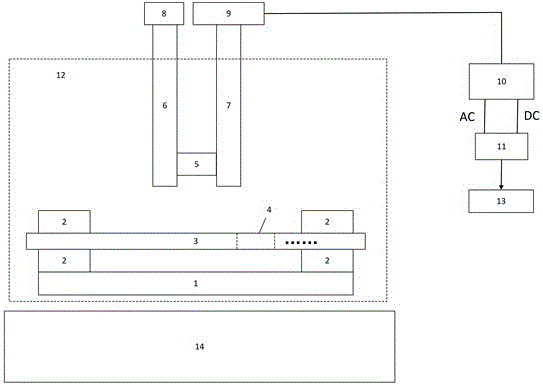
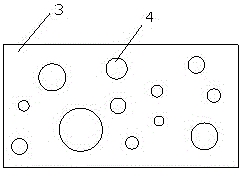
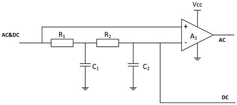
[0029] like figure 1 As shown, a current transformer based on a magnetically controlled grating light valve of the present invention includes a high-voltage bus 14, a light source 8, a magnetically controlled grating light valve 12, a photoelectric receiver 9, an AC / DC separation module 10, a divider 11 and The output voltage value is 13. The AC / DC separation module 10 is an AC / DC separation module. The output end of the light source 8 is connected to the input end of the magnetically controlled grating light valve 12, the output end of the magnetically controlled grating light valve 12 is connected to the input end of the photoelectric receiver 9, and the output end of the photoelectric receiver 9 is connected to the AC / DC separation module 10 The input end of the AC / DC separation module 10 is connected to the input end o...


PUM


Abstract

The invention discloses a magnetic control grating light valve based current transformer. The magnetic control grating light valve based current transformer comprises a high voltage bus, a light source, a magnetic control grating light valve, a photoelectric receiver, an AC (Alternating Current) / DC(Direct Current) separating module, a divider and an output voltage value; an output end of the light source is connected with an input end of the magnetic control grating light valve; an output end of the magnetic control grating light valve is connected with an input end of the photoelectric receiver; an output end of the photoelectric receiver is connected with an input end of the AC / DC separating module; an output end of the AC / DC separating module is connected with an input end of the divider; an output end of the divider is connected with the output voltage value; the high voltage bus is parallel to the magnetic control grating light valve and the light voltage bus is arranged on one side of the magnetic control grating light valve; the light source and the photoelectric receiver are arranged on the other side of the magnetic control grating light valve. The magnetic control grating light valve based current transformer not requires energy supply. Meanwhile the invention also provides a bus current detection method through the magnetic control grating light valve based current transformer. The bus current detection method is easy to operate and low in cost.

Description

technical field [0001] The invention belongs to the field of power system monitoring, and specifically relates to a current transformer based on a magnetically controlled grating light valve and a method for detecting bus current. Background technique [0002] With the rapid development of the national economy, the demand for electricity is increasing day by day. The power system has an information and control system in each link, which measures, adjusts, controls, protects, communicates and dispatches the production process of electric energy to ensure that users obtain safe, economical and high-quality electric energy. Measuring current is a routine means of obtaining information about power systems. At present, the traditional electromagnetic current transformers widely used in power systems have problems such as magnetic saturation, electromagnetic interference, small dynamic range, narrow frequency band range, and inflammability and explosion. [0003] In order to sol...

Claims


Application Information

Patent Timeline
Patent Type & Authority Patents(China)
IPC IPC(8): G01R15/24G01R19/00
Inventor 韦朴程澄孙小菡单雪康
Owner SOUTHEAST UNIV
Why Eureka
Eureka Blog
Learn More