Voltage and current combined sensor and voltage and current detection system

A voltage, current, and voltage detection technology, applied in the electric power field, can solve the problems of high insulation design cost, poor safety, and high insulation performance requirements of transformers, and achieve the effect of reducing insulation design cost and improving safety

Active Publication Date: 2018-07-03
STATE GRID CHONGQING ELECTRIC POWER CO ELECTRIC POWER RES INST +2
View PDF6 Cites 0 Cited by
  • Summary
  • Abstract
  • Description
  • Claims
  • Application Information

AI Technical Summary

Problems solved by technology

[0003] At present, voltage and current measurements in transmission lines are mainly realized through transformers, while traditional transformers need to be directly electrically connected to transmission lines, which require high insulation performance of transformers, resulting in high insulation design costs, and transformers need to be connected with power transmission lines. The line is directly connected electrically, which is poor in safety

Method used


Image

  • Voltage and current combined sensor and voltage and current detection system
  • Voltage and current combined sensor and voltage and current detection system
  • Voltage and current combined sensor and voltage and current detection system

Examples


Embodiment 1

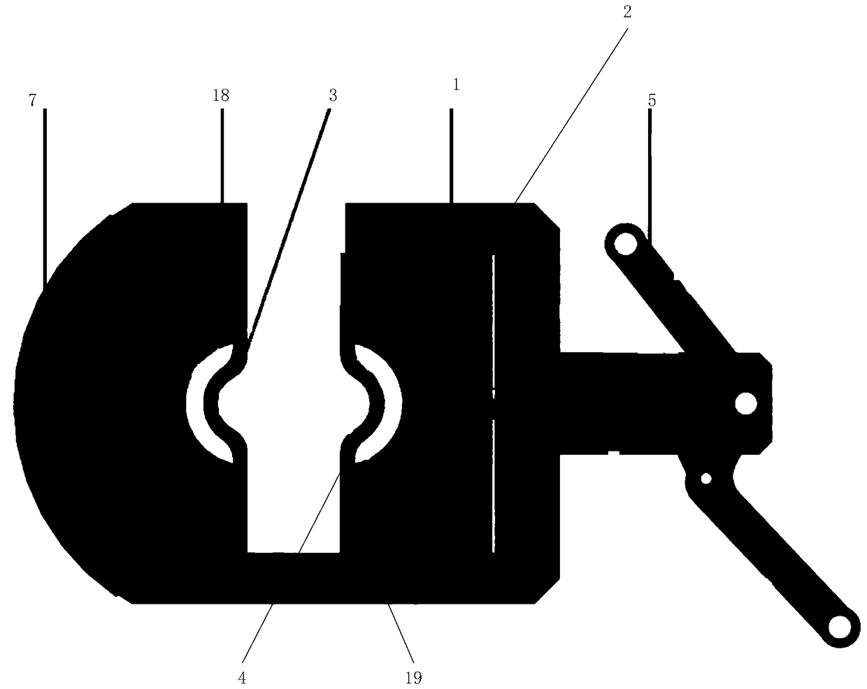
[0050] In this embodiment, a combined voltage and current sensor is shown, please refer to Figure 1 to Figure 5 , The voltage and current combined sensor includes: a fixed bracket 1, a movable bracket 2, a first wire fixing mechanism 3 and a second wire fixing mechanism 4, a locking handle 5, a linkage mechanism 6, an electric field sensor probe 7 and a magnetic field sensor probe.

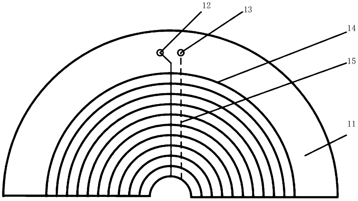
[0051] The electric field sensor probe 7 includes: a PCB substrate 11, a first electrode group, a second electrode group, a first terminal 12 and a second terminal 13, and the first electrode group includes a plurality of serially connected semi-annular structures. The first electrode 14, and the second electrode group includes a plurality of second electrodes 15 in a semi-circular structure connected in series.

[0052] The magnetic field sensor probe includes a first iron core 18, a second iron core 19, a Rogowski coil, a third terminal and a fourth terminal;

[0053]The first iron core 18 is ...

Embodiment 2

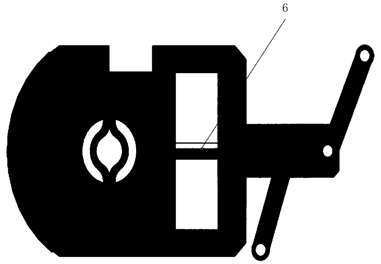
[0068] In this embodiment, a voltage and current detection system is provided, please refer to Image 6 , The voltage and current detection system includes: a voltage detection device 61 , a current detection device 62 and a combined voltage and current sensor 63 .

[0069] For the specific structure and related functions of the combined voltage and current sensor 63 , please refer to the combined voltage and current sensor shown in Embodiment 1, which will not be repeated here.

[0070] The voltage detecting device 61 is connected to the combined voltage and current sensor 63 , and the current detecting device 62 is connected to the combined voltage and current sensor 63 .

[0071] The voltage detection device 61 is configured to process the potential difference signal output by the voltage-current combined sensor 63 to obtain the voltage of the transmission line to be detected.

[0072] The current detection device 62 is configured to process the induced electromotive force...


PUM


Abstract

The application provides a voltage and current combined sensor and a voltage and current detection system. The voltage and current combined sensor comprises a fixed support, a movable support, a first lead fixing mechanism, a second lead fixing mechanism, a locking handle, a linkage mechanism, an electric field sensor probe and a magnetic field sensor probe. The electric field sensor probe comprises a PCB substrate, a first electrode group, a second electrode group, a first binding post and a second binding post; the first electrode group comprises a plurality of semiorbicular first electrodes successively in series connection, and the second electrode group comprises a plurality of semiorbicular first electrodes successively in series connection; the magnetic field sensor probe comprises a first iron core, a second iron core, a Rogowski coil, a third binding post and a fourth binding post. The voltage and current combined sensor reduces insulation design costs, does not need to be in direct electrical connection with a power transmission line to be detected, and improves safety.

Description

technical field [0001] The present application relates to the field of electric power, in particular to a voltage and current combined sensor and a voltage and current detection system. Background technique [0002] The voltage and current measurement of the transmission line is closely related to the safe, reliable and economical operation of the power system, and is an important link in the maintenance of the power system. An efficient and safe measurement method is an effective way to improve maintenance efficiency and grid power supply quality. [0003] At present, voltage and current measurements in transmission lines are mainly realized through transformers, while traditional transformers need to be directly electrically connected to transmission lines, which require high insulation performance of transformers, resulting in high insulation design costs, and transformers need to be connected with power transmission lines. The line is directly connected electrically, wh...

Claims


Application Information

Patent Timeline
Patent Type & Authority Patents(China)
IPC IPC(8): G01R19/25
CPCG01R19/25
Inventor 李松浓周强侯兴哲周孔均王毅何国军胡晓锐宫林郑可梁星何为刘型志
Owner STATE GRID CHONGQING ELECTRIC POWER CO ELECTRIC POWER RES INST
Why Eureka
Try Eureka