Eureka AIR delivers breakthrough ideas for toughest innovation challenges, trusted by R&D personnel around the world.

Aircraft seat slide rail position detection device and its measuring method

A detection device and aircraft seat technology, which is applied in the field of aircraft, can solve problems such as inaccurate installation position of slide rails, different deviations of slide rail positions, large installation position deviations, etc., and achieve the level of product quality control. The effect of less frequency and easy disassembly

Active Publication Date: 2017-06-09
SHANGHAI AIRCRAFT MFG +1
View PDF6 Cites 0 Cited by
  • Summary
  • Abstract
  • Description
  • Claims
  • Application Information

AI Technical Summary

Problems solved by technology

However, during the development of the aircraft project and the actual mass production process, due to the large deviation of the installation position of the seat slide rail in the large component, after the large component is positioned according to the slide rail, the shape of the fuselage between adjacent large components Serious misalignment between the axes of the long truss and the long truss, which cannot meet the requirements for docking installation, and even lead to the scrapping of the seat slide rails of the middle fuselage
Until the frame is installed, the installation position of the slide rail is still not accurate, and the deviation of the slide rail position on each aircraft is not the same
When the aircraft enters the mass production stage, the docking quality of the whole aircraft cannot be guaranteed
[0003] The deviation of the seat slide rail has actually happened repeatedly in the development of the aircraft. Although measures have been taken to correct it many times, it has not been effectively controlled so far.

Method used


Image

  • Aircraft seat slide rail position detection device and its measuring method
  • Aircraft seat slide rail position detection device and its measuring method
  • Aircraft seat slide rail position detection device and its measuring method

Examples


Embodiment Construction

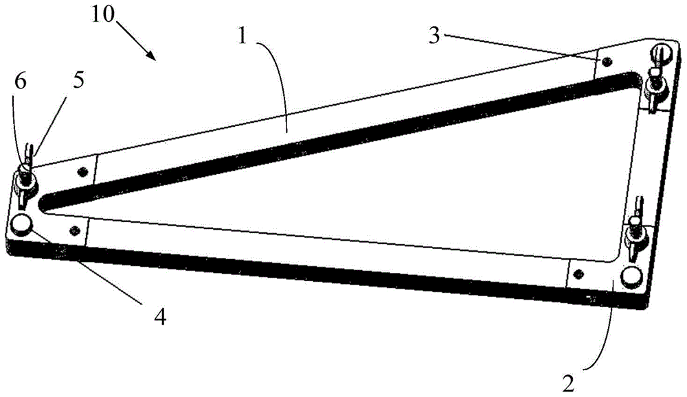
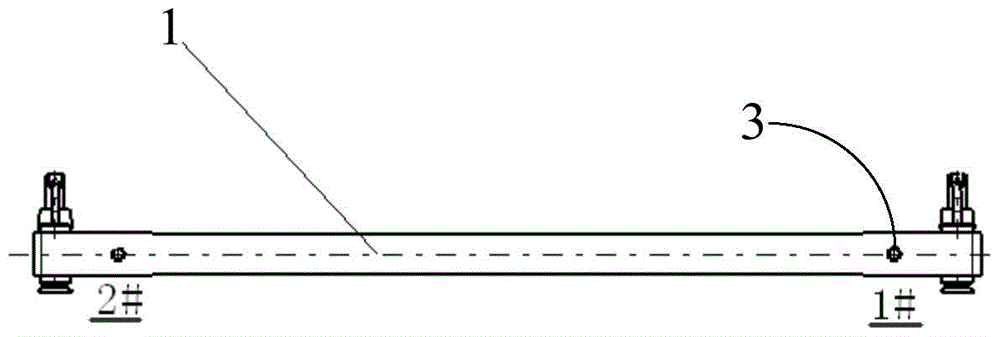
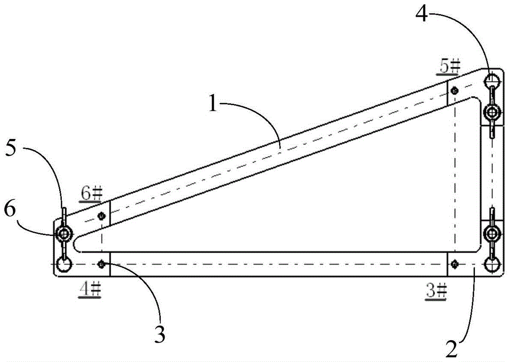
[0024] Figure 1 to Figure 3 Shown is a detection device 10 for the position of an aircraft seat slide rail according to a preferred embodiment of the present invention. This detection device 10 comprises detachably fixedly installed on two parallel seat slide rails 20 ( Figure 4 and Figure 5 ) above the body 1, the body 1 is provided with at least one positioning installation part 2 on each seat slide rail and a plurality of measurement holes 3 adjacent to the positioning installation part 2, and the ball seat of the laser tracker is inserted into the measurement hole 3 in. When measuring, the laser tracker located outside the frame (such as on the ground) can measure the coordinates of the ball seat through lasers, and then obtain multiple measurement holes corresponding to the X value and Z value in the overall machine coordinate system. In the illustrated embodiment, the body 1 of the detection device 10 is configured in a triangular shape, including a positioning ins...


PUM


Abstract

The invention provides a detection device and a measurement method for the position of slide rails of aircraft seats. The detection device is used in conjunction with a laser tracker, and includes a body detachably fixed and installed above two parallel seat slide rails, and the body is provided with at least one positioning installation part on each seat slide rail and A plurality of measuring holes adjacent to the positioning installation part are used for inserting the ball seat of the laser tracker, wherein the plurality of measuring holes respectively correspond to measuring the X value and the Z value in the coordinate system of the whole machine. The detection device of the present invention is convenient to use the laser tracker for measurement, and the measurement accuracy is high; the laser has good accessibility, high safety, and there are many measurement points on the tooling, and the number of transfer stations is small when the laser tracker is used for measurement, and there is no need to mount the equipment The height goes to the inside of the fuselage, and even does not need to be raised; in addition, the detection device is easy to install and disassemble, light and firm, and easy to carry to the supplier.

Description

technical field [0001] The present invention generally relates to the technical field of aircraft, in particular to a detection device and a measurement method for the position of slide rails of aircraft seats. Background technique [0002] In the final assembly of some types of aircraft, the cross-joint scheme is usually adopted, and the seat slide rail is used as the docking positioning of the nose, front fuselage, middle fuselage, middle and rear fuselage, and rear fuselage on the assembly tooling. Therefore, the installation accuracy of the seat rail itself is very important. However, during the development of the aircraft project and the actual mass production process, due to the large deviation of the installation position of the seat slide rail in the large component, after the large component is positioned according to the slide rail, the shape of the fuselage between adjacent large components Serious misalignment between the axis of the long truss and the long trus...

Claims


Application Information

Patent Timeline
Patent Type & Authority Patents(China)
IPC IPC(8): G01B11/00
Inventor 高国志戴乐寅潘龙飞
Owner SHANGHAI AIRCRAFT MFG
Why Eureka
Eureka Blog
Learn More