Small mechanical part shape and position error detection device and detection method thereof

A technology for mechanical parts, shape and position error, applied in the field of mechanical parts shape and position error detection equipment, can solve the problems of expensive detection equipment, inability to achieve online detection, affecting the final accuracy of measurement results, etc., to improve detection accuracy and detection accuracy. , Improve detection efficiency and detection accuracy, and achieve the effect of automatic online detection

Inactive Publication Date: 2015-02-04
济宁中科智能科技有限公司
View PDF11 Cites 26 Cited by
  • Summary
  • Abstract
  • Description
  • Claims
  • Application Information

AI Technical Summary

Problems solved by technology

However, the detection equipment can only detect flatness, and it is still difficult to detect other shape errors and position errors
In addition, the horizontal workbench where the sample to be tested needs to be moved during the measurement process. If there is movement, vibration cannot be avoided, and vibration will definitely affect the final accuracy of the measurement results.
[0008] Through the comparison and analysis of the above various detection methods, the problem of the traditional detection method of contact detection is that it cannot detect all the shape and position errors in one device, which is inefficient and the detection accuracy is not high; The traditional detection method not only cannot realize online detection, but also has high environmental requirements and expensive detection equipment.

Method used


Image

  • Small mechanical part shape and position error detection device and detection method thereof
  • Small mechanical part shape and position error detection device and detection method thereof
  • Small mechanical part shape and position error detection device and detection method thereof

Examples


Embodiment Construction

[0048] Embodiments of the present invention are further described below in conjunction with accompanying drawings:

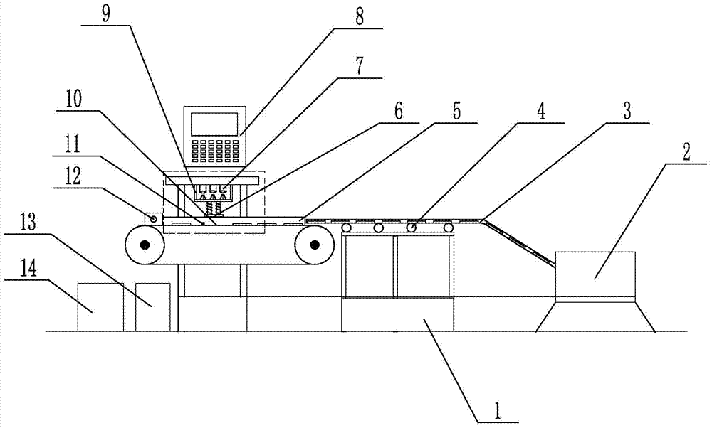
[0049] Such as figure 1 As shown, the shape error detection device for small mechanical parts of the present invention includes a base 1, a vibration plate 2 is installed on one end of the base 1, and the discharge port of the vibration plate 2 is connected to the feed end of the material channel 3 , the material channel 3 is supported by the material channel support rod 4 installed on the top of the middle position of the base 1, the discharge end of the material channel 3 corresponds to the feed end of the conveyor belt 10, and the two sides of the conveyor belt 10 are equipped with limit plates 5, The detection fixture 9 is installed on the top of the conveyor belt 10, and the detection fixture 9 is installed on the end of the base 1. The front, rear, left, right and top of the detection fixture 9 are equipped with laser displacement sensors 7, and the bottom...


PUM


Abstract

The invention relates to mechanical part shape and position error detection equipment and particularly relates to a small mechanical part shape and position error detection device and a detection method thereof. The base of the detection device is equipped with a vibration disk which is connected to a material channel, and the material channel is supported by a material channel supporting rod installed at the top of the base and is corresponding to the feeding end of a conveying belt. Two sides of the conveying belt are equipped with limiting plates. A detection fixed frame is installed above the conveying belt and is internally equipped with a laser displacement sensor. The bottom of the detection fixed frame is equipped with an electromagnet, and a photoelectric switch corresponding to the electromagnet is arranged on the conveying belt. The material out end of the conveying belt is provided with a cylinder block, and the electromagnet, the conveying belt, the laser displacement sensor, the photoelectric switch and the cylinder block are connected with a control system. According to the small mechanical part shape and position error detection device and the detection method, the online detection of the multiple shape and position errors of a small regular part can be achieved, the manual intervention is not needed in the detection process, unqualified parts can be eliminated automatically, the automatic detection is realized, and the detection efficiency and accuracy are improved.

Description

technical field [0001] The invention relates to a shape and position error detection device for mechanical parts, in particular to a shape and position error detection device and detection method for small mechanical parts. Background technique [0002] The shape and position errors of mechanical parts include shape errors such as flatness and straightness, and position errors such as parallelism and perpendicularity. The detection methods of shape and position errors of general parts are divided into two categories: contact detection and non-contact detection. The traditional methods of contact detection methods mainly include: plug gauge ruler measurement, meter measurement method, liquid level method; common non-contact measurement methods include beam plane method, plane interferometer, spirit level, laser interferometer, white light interferometer, etc. [0003] The detection of the convex surface by the plug gauge ruler is to place the workpiece to be measured on the ...

Claims


Application Information

Patent Timeline
IPC IPC(8): G01B11/00G01B11/30G01B11/26
Inventor 穆范全李卫民潘云龙胡悦魏循中徐回
Owner 济宁中科智能科技有限公司
Why Eureka
Try Eureka