Method for Improving Engine Efficiency and Engine Compatible with the Method

An engine and power technology, which is applied in the direction of combustion engines, machines/engines, mechanical equipment, etc., can solve the problems that the energy in the initial combustion period is not effectively used, the mass and size of the engine increase, and the service life of the engine is affected, so as to save fuel. Effect of reducing vibration and improving service life

Inactive Publication Date: 2017-06-20
张玉辉 +1
View PDF5 Cites 0 Cited by
  • Summary
  • Abstract
  • Description
  • Claims
  • Application Information

AI Technical Summary

Problems solved by technology

To solve this problem, the flywheel must have a large enough moment of inertia, which in turn leads to an increase in overall engine mass and size
The use of multi-cylinder engines can make up for the above shortcomings, but at the same time, there are also problems such as complex structure, difficult process, and high technical requirements.
[0021] Moreover, the current common internal combustion engine still has the problem of low energy efficiency, which is manifested as:
[0022] 1. The piston of the engine reaches the top dead center, and when the compression ratio reaches a certain point, it is ignited or compression-ignited (the diesel engine adopts compression-ignition technology), not only the energy in the initial combustion period is not effectively utilized, but also the cylinder pressure increases, which affects the service life of the engine;
[0023] 2. Due to the difference in fuel quality, the optimal compression ratio of the fuel in the cylinder is different. If a vehicle that requires high-grade gasoline accidentally uses low-grade oil, it may cause detonation in advance and cause damage to the engine.

Method used


Image

  • Method for Improving Engine Efficiency and Engine Compatible with the Method
  • Method for Improving Engine Efficiency and Engine Compatible with the Method
  • Method for Improving Engine Efficiency and Engine Compatible with the Method

Examples


Embodiment 1

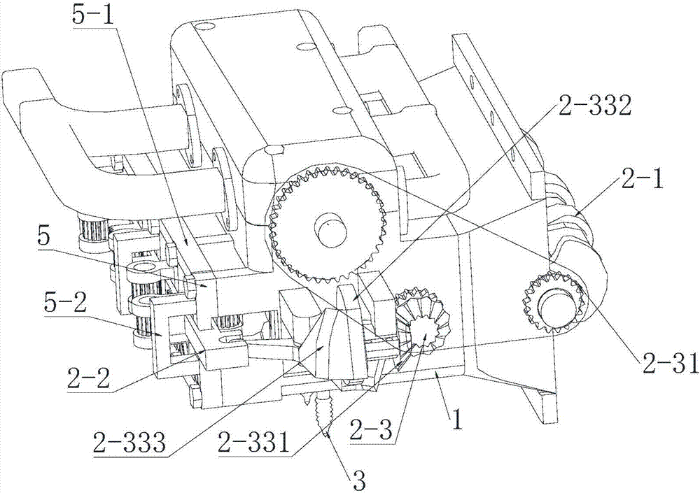
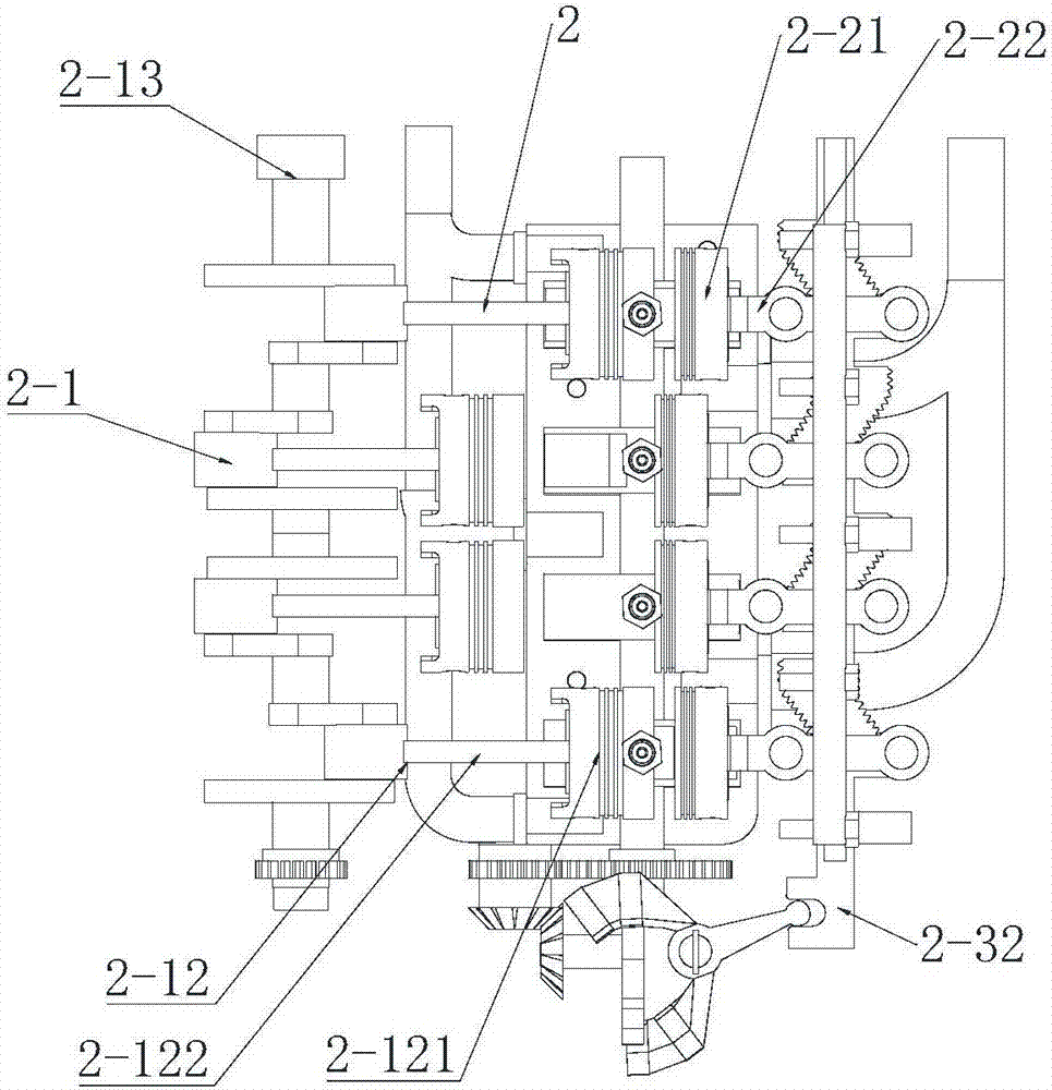
[0072] Such as Figure 1-Figure 10 As shown, the engine of the present invention adopts a four-cylinder structure, including an engine frame 1 and a power transmission system 2, a spark plug 3, a fuel injector and an intake and exhaust system 4 arranged on the engine frame 1, and the power transmission system 2 includes a The crank linkage mechanism 2-1 of the system and the power acceleration compensation device 2-2 corresponding to the crank linkage mechanism; the crank linkage mechanism 2-1 includes the body group 2-11, the piston connecting rod group 2-12 and the crankshaft flywheel group 2-13, the body group includes a crankcase 2-111, a cylinder block 2-112, and a cylinder head connected and matched with the cylinder block, and the piston connecting rod group 2-12 includes the main power piston 2-121 arranged in the cylinder body and the main power piston 2-121 connected with the main cylinder body. The active power piston connecting rod 2-122 that is movably connected t...

Embodiment 2

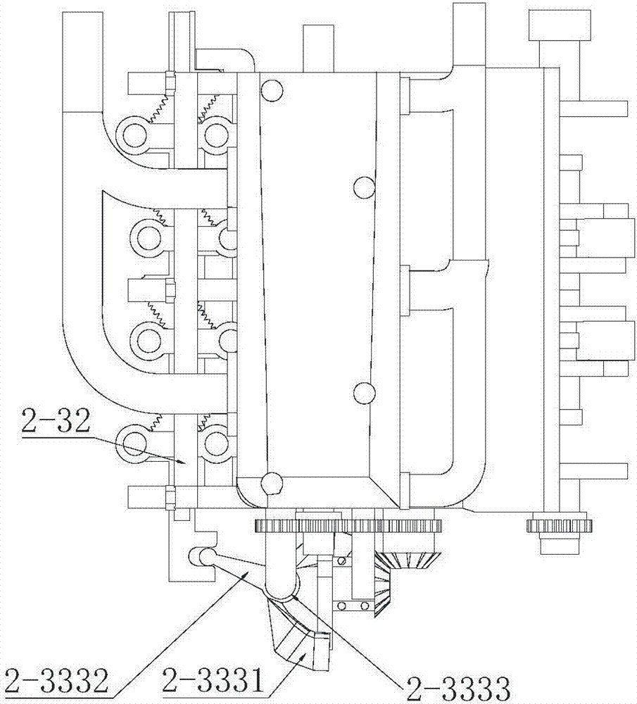
[0082] Such as Figure 12-Figure 16 As shown, this embodiment is different from the design of the swing follower cam mechanism in Embodiment 1. The swing follower cam mechanism 2-33 includes a rotating sleeve 2-334 driven by the output gear of the sprocket drive mechanism, a swing Rod 2 2-335, swing fulcrum 2 2-336 is arranged on the swing rod 2, one end of the swing rod 2 is movably connected with the rotating sleeve, and the other end is connected with the slide bar; The axis of 334 forms an annular groove 2-337 with a certain inclination angle, and one end of the swing rod 2 is provided with a sliding piece that is slidably connected with the annular groove. Through the rotation of the rotating sleeve, the sliding piece slides along the track of the annular groove, thereby The two pairs of slide bars are driven to push and pull the swing bar.

[0083] In this example, if Figure 19 As shown, in order to increase the stability of the rotating sleeve driven by the output ge...

Embodiment 3

[0085] Such as Figure 17 and Figure 18 As shown, this embodiment is different from the design of the intake and exhaust system of Embodiment 1. The intake and exhaust system 4 includes intake and exhaust passages 4-4 and 4-5 connected to the cylinder block. Valves 4-6 are respectively arranged in the gas channel, and return springs 4-7 are installed on the valves, and the end of the valves is connected with a cam mechanism 4-8, which is used to drive the opening or closing of the valves; the cam mechanism 4-8 includes a cam 4-81 And lever 4-82, one end of the lever and the terminal movable push-fit of valve, the axle of cam and crankshaft are linked by transmission mechanism, and the opening and closing of valve are driven by crankshaft, complete the intake and exhaust function of engine.

[0086] The invention greatly improves the existing engine technology, has low manufacturing cost, can optimize the material consumption of the existing engine, and adds a power accelerat...


PUM


Abstract

The invention discloses a method for improving engine efficiency and an engine matched with the method, including an engine frame, a power transmission system, a spark plug, a fuel injector and an intake and exhaust system, and the feature is that the power transmission system includes a crank connecting rod mechanism and Power acceleration compensation device; the crank-link mechanism includes a body group, a piston connecting rod group and a crankshaft flywheel group, and the body group includes a crankcase, a cylinder block, and a cylinder head connected with the cylinder block; the power acceleration compensation device includes The acceleration compensation piston and the acceleration compensation piston rod are arranged in the same cylinder body, and the acceleration compensation transmission mechanism is connected between the acceleration compensation piston rod and the crankshaft, and the crankshaft drives the acceleration compensation piston to move in the compensation space inside the cylinder body through the acceleration compensation transmission mechanism. The invention utilizes the power acceleration compensation device to adjust the angle between the crankshaft and the cylinder to re-ignite, increase the power of the engine, reduce the idle speed and dynamic load speed of the engine, and realize the purpose of energy saving.

Description

technical field [0001] The invention relates to the technical field of engines, and more specifically relates to a method capable of improving engine efficiency and a corresponding high-efficiency and energy-saving engine. Background technique [0002] An engine is a machine that can convert other forms of energy into mechanical energy. It has experienced three development stages: steam engine, external combustion engine and internal combustion engine. There are many types of internal combustion engines, and common gasoline engines and diesel engines are typical internal combustion engines. However, due to the different properties of gasoline and diesel, there are differences in the working principle and structure of the engine. [0003] 1. The working principle of a gasoline engine is to mix air and gasoline in a certain proportion to form a good mixture, which is sucked into the cylinder during the intake stroke, and the mixture is compressed and ignited to generate heat ...

Claims


Application Information

Patent Timeline
Patent Type & Authority Patents(China)
IPC IPC(8): F02B33/22
Inventor 张玉辉陈阳
Owner 张玉辉
Why Eureka
Try Eureka