An automatic rotary net filling and stewing machine

An automatic, head-to-head machine technology, applied to screen printing machines, printing machines, rotary printing machines, etc., can solve the problems of hard damage to the substrate, low printing efficiency, and low speed of the printing machine, so as to prevent the formation of nodules and ensure The effect of printing quality and improving production efficiency

Inactive Publication Date: 2016-05-25
郝强
View PDF6 Cites 0 Cited by
  • Summary
  • Abstract
  • Description
  • Claims
  • Application Information

AI Technical Summary

Problems solved by technology

In this process, if the braised head chuck clamps the stewed head incorrectly, it will lead to improper combination of the rotary screen and the stewed head
However, in the existing steaming machine, the steaming head is fixed on the steaming chuck during the whole steaming process, and only moves along the frame with the chuck frame in a reciprocating linear motion, so it is not easy to find the rotary net in time. Improperly installed stewed head
In the subsequent printing process, if the brazing heads at both ends of the rotary screen are not installed correctly, if the printing machine rotates at a high speed, the rotary screen will be damaged and the printing waste of the substrate will be caused.
And if the speed of the printing machine is low, the printing efficiency will be low
In addition, during the bonding process of the glue on the head and the two ends of the rotary screen, the glue on the outer surface of the head is likely to form nodules, and in the subsequent printing process, the nodules are likely to cause serious damage to the substrate

Method used


Image

  • An automatic rotary net filling and stewing machine
  • An automatic rotary net filling and stewing machine
  • An automatic rotary net filling and stewing machine

Examples


Embodiment Construction

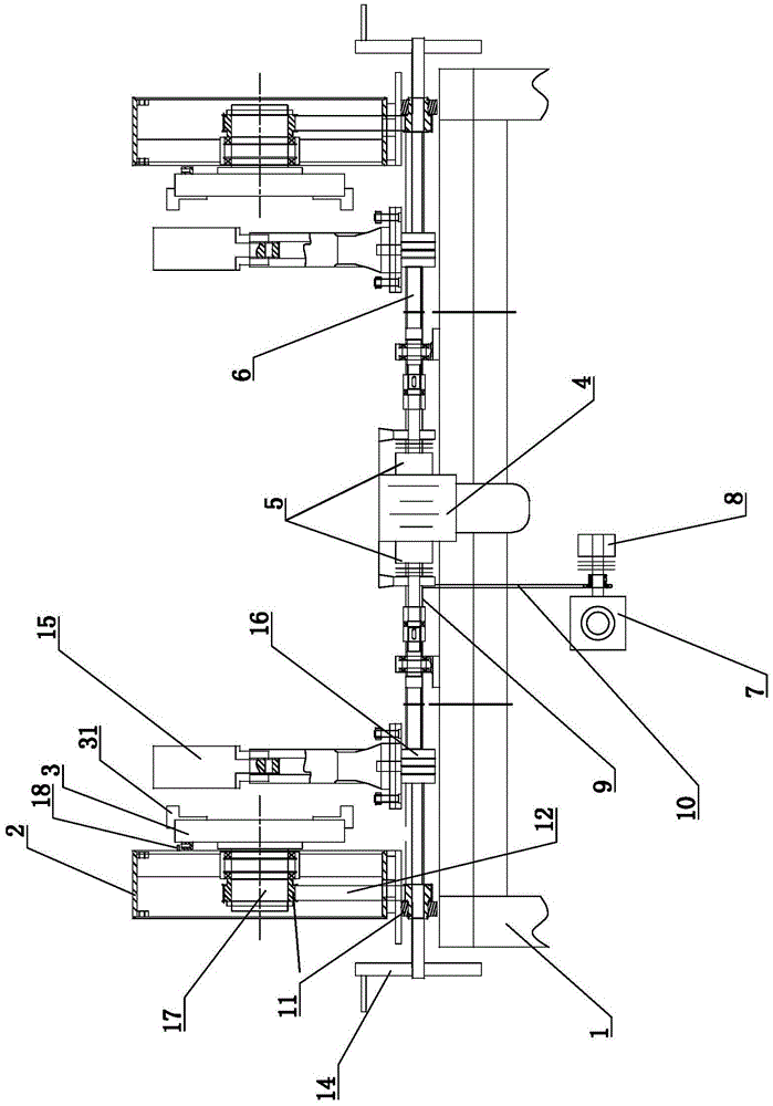
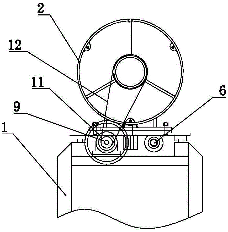
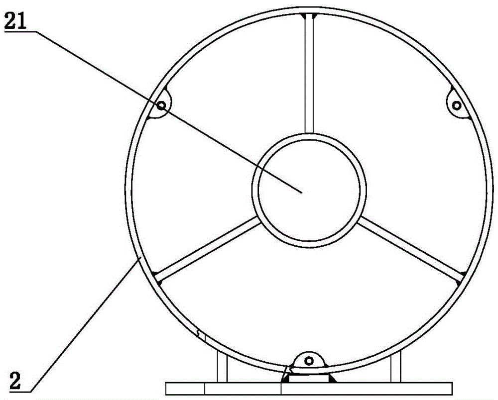
[0025] figure 1 is a structural schematic diagram of the present invention; figure 2 yes figure 1 Schematic diagram of the side view structure; image 3 yes figure 1 Schematic diagram of the structure of the chuck holder in ; Figure 4 yes figure 1 Schematic diagram of the chuck structure in .

[0026] refer to figure 1 , figure 2 , image 3 as well as Figure 4 , the automatic rotary net head stewing machine of the present invention comprises a frame 1, the two ends of the frame 1 are respectively provided with chuck frames 2, and the frame 1 between the two chuck frames 2 is provided with two holders. The rotary screen bracket 15 of the rotary screen, the two ends of the frame 1 are respectively fixedly provided with guide rails (not shown in the figure), and two chuck frames 2 are slidably matched with the two guide rails respectively; Transmission device and the first power device, the first transmission device cooperates with two chuck frames 2 respectively, t...


PUM


Abstract

The invention discloses an automatic positioning disk mounting machine for a rotary screen. The automatic positioning disk mounting machine for the rotary screen comprises a machine frame, wherein chuck holders are slidably arranged at two ends of the machine frame respectively; two rotary screen brackets are arranged at the position, between the two chuck holders, on the machine frame; a first transmission device and a first power device are arranged on the machine frame; the first transmission device is matched with the two chuck holders respectively; the first power device drives the two chuck holders to synchronously move toward each other through the first transmission device; a rotatable positioning disk chuck is mounted on each chuck holder; a second transmission device and a second power device are further arranged on the machine frame; the second transmission device is matched with the positioning disk chucks respectively; the second power device drives the two positioning disk chucks to synchronously rotate around the central lines of the positioning disk chucks through the second transmission device. According to the automatic positioning disk mounting machine for the rotary screen, the situation that a positioning disk is unaligned with the rotary screen can be timely discovered, so that the rotary screen provided with the unaligned positioning disk is prevented from being transferred to the subsequent printing process.

Description

technical field [0001] The invention relates to the technical field of textile printing and dyeing equipment, in particular to an automatic rotary screen head-stacking machine in rotary screen printing. Background technique [0002] In rotary screen printing, it is a very important process to put the heads on the two ends of the rotary screen after gluing. The existing automatic rotary screen heads are equipped with chuck frames at both ends, and the two chuck frames are Braised head chucks are respectively fixed on the upper frame, and a transmission device and a power device are arranged on the frame. During the steaming process on the rotary net, the two steaming heads are respectively fixed on the steaming chucks at both ends, and then the transmission device drives the two chuck frames to move synchronously and oppositely through the power device, and the steaming heads are pushed straight into the rotary net Inside, then fix the rotary net and the stewing head. In th...

Claims


Application Information

Patent Timeline
Patent Type & Authority Patents(China)
IPC IPC(8): B41F15/38
Inventor 郝强
Owner 郝强
Why Eureka
Try Eureka