
Universal elastic fixed rod

An elastic fixation and rod fixation technology, applied in the direction of fixator, internal fixator, internal bone synthesis, etc., can solve the problems of poor resistance to elastic attenuation, only about 3 degrees, and high production cost, and achieve strong resistance to elastic attenuation. Effect

Inactive Publication Date: 2015-02-04
李照文
View PDF5 Cites 4 Cited by
  • Summary
  • Abstract
  • Description
  • Claims
  • Application Information

AI Technical Summary

Problems solved by technology

However, there are still many defects in the existing dynamic internal fixators for the spine. For example, some fixators can only provide activities in a certain direction (such as Coflex can only provide sagittal extension and flexion); if the spring system fixator is resistant to elastic attenuation The ability is poor, and the production cost is high; for example, the elastic rod fixer is cylindrical, although it can rely on the elasticity of the material itself to carry out weak universal activities, but its range of activities is small, only about 3 degrees, far smaller than the extension of the human spine. Flexion, rotation and other range of motion, it is difficult to guarantee low complications and good long-term effects

Method used


Image

  • Universal elastic fixed rod
  • Universal elastic fixed rod
  • Universal elastic fixed rod

Examples


Embodiment Construction

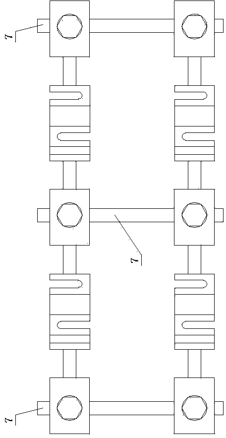
[0021] The universal elastic fixing rod is composed of a U-shaped deformation structure, a twisted connecting plate 3, and a cylinder 4, and the cylinder 4 is fixed by tightening the nut 5 and the fixing screw 6, and it is characterized in that: the U-shaped deformation structure consists of at least one A vertical U-shape 1 and a horizontal U-shape 2 are formed. When the two sides of the U-shaped deformed structure are respectively fixed with twisted connecting plates 3, the other ends of the twisted connecting plates 3 are respectively fixed with cylinders 4; when the U-shaped deformed structure When one side of the U-shaped deformation structure is fixedly connected with a twisted connecting plate 4, the other side of the U-shaped deformation structure is directly connected with the cylinder 4. The vertical U-shape 1 provides rotation in the vertical direction, the horizontal U-shape 2 provides rotation in the horizontal direction, and the twisted connecting plate 3 provides...


PUM


Abstract

The invention relates to a universal elastic fixed rod, and belongs to the technical field of implants in a human body for medical apparatus and instruments. The universal elastic fixed rod comprises a U-shaped deformation structure, a torsion connection plate and a cylinder, wherein the U-shaped deformation structure is composed of at least one vertical U shape and a horizontal U shape; when two sides of the U-shaped deformation structure are fixedly connected with the torsion connection plate, the other end of the torsion connection plate is fixedly connected with the cylinder; and when one side of the U-shaped deformation structure is fixedly connected with the torsion connection plate, and the other side of the U-shaped deformation structure is directly connected with the cylinder. According to the universal elastic fixed rod, elastic movement in each direction, such as anteflexion, rear protraction, left and right lateral bending, rotation and the like of an operation section in a sagittal view can be achieved; the elastic movement is full; the postoperative elasticity attenuation resistance is strong; the universal elastic fixed rod can be applied to one or more segments of spines, and can also be applied to dynamic fixation of fracture dislocation; and the problems that various dynamic spinal internal fixtures used at present cannot reserve full elastic movement of the spines in each direction, and the elasticity attenuation resistance is weak are solved.

Description

technical field [0001] The invention relates to a universal elastic fixing rod, which belongs to the technical field of implants in the human body of medical devices. Background technique [0002] At present, spinal fusion technology has achieved good results in the treatment of spinal diseases, especially low back pain and lumbar instability, with a fusion rate of over 90%. However, studies have shown that its clinical efficacy has not reached the expected value; moreover, rigid internal fixation and spinal fusion may cause complications such as accelerated degeneration of adjacent segments, internal fixation failure, and postoperative pseudarthrosis formation. In view of this, dynamic fixation of the spine is becoming a popular technique in the treatment of degenerative lumbar diseases in recent years. The implantation of the dynamic internal fixation system can dynamically fix the spine without sacrificing the immediate stability of the spine. After surgery, it can dispe...

Claims


Application Information

Patent Timeline
IPC IPC(8): A61B17/70A61F2/44
CPCA61B17/7002A61B17/704A61F2/442
Inventor 李照文
Owner 李照文
Learn More