
A bidirectional dcdc converter and optical storage system

A technology for optical storage systems and converters, which is applied in the field of bidirectional DCDC converters and optical storage systems, and can solve problems such as the inability to achieve high power utilization in distributed power supply systems, low configuration voltage, and high circuit costs

Active Publication Date: 2016-11-30
SUNGROW POWER SUPPLY CO LTD
View PDF6 Cites 1 Cited by
  • Summary
  • Abstract
  • Description
  • Claims
  • Application Information

AI Technical Summary

Problems solved by technology

[0002] The current situation of multiple new energy grid-connected power generation has brought a certain burden to the stability of the large power grid. In order to reduce the proportion of new energy grid-connected and increase its self-generation and self-use rate, the power supply system in the prior art mostly uses energy storage equipment and A distributed power supply system that combines a variety of new energy grid-connected power generation, because the energy storage equipment needs to be replaced manually, and its configuration voltage is low, generally 48V, so its charging and discharging requires a DCDC converter with a high boost ratio
[0003] The two sets of charge-discharge DCDC converters or bidirectional DCDC converters traditionally used can make the energy storage equipment achieve a higher utilization rate, but can only take power from a certain place to charge and discharge the energy storage equipment. Bidirectional DCDC The converter will inevitably have power loss in the charging or discharging process, and the circuit cost of the two sets of charging and discharging DCDC converters is relatively high, so neither of them can achieve high power utilization of the entire distributed power supply system

Method used


Image

  • A bidirectional dcdc converter and optical storage system
  • A bidirectional dcdc converter and optical storage system
  • A bidirectional dcdc converter and optical storage system

Examples


Embodiment Construction

[0041] The following will clearly and completely describe the technical solutions in the embodiments of the present invention with reference to the accompanying drawings in the embodiments of the present invention. Obviously, the described embodiments are only some, not all, embodiments of the present invention. Based on the embodiments of the present invention, all other embodiments obtained by persons of ordinary skill in the art without making creative efforts belong to the protection scope of the present invention.

[0042] An embodiment of the present invention provides a bidirectional DCDC converter to realize high power utilization of the entire distributed power supply system.

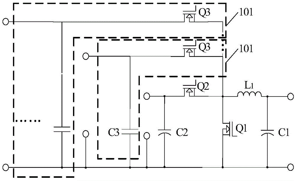
[0043] Specifically, such as figure 1 As shown, the bidirectional DCDC converter includes:

[0044] a first capacitor C1 and a first inductor L1 connected to each other at one end; both ends of the first capacitor C1 serve as low-voltage input and output ports of the bidirectional DCDC convert...


PUM


Abstract

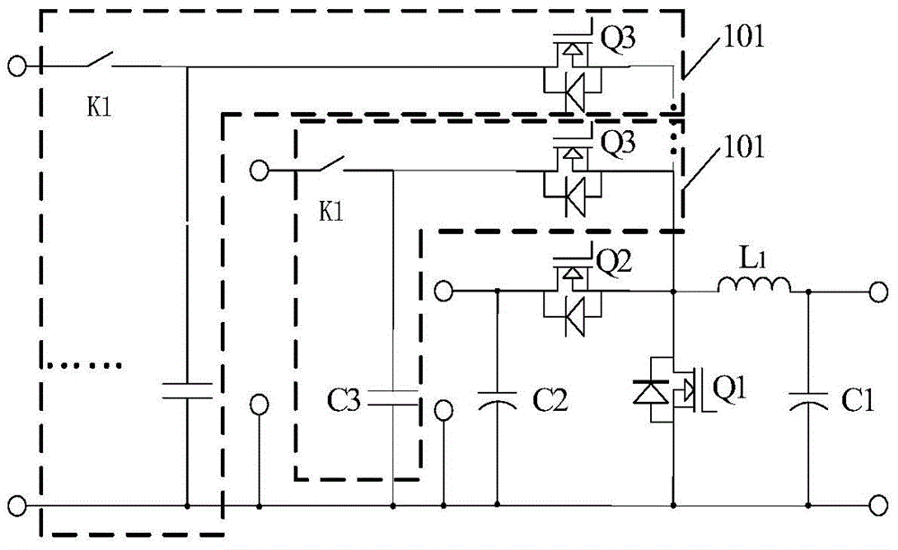
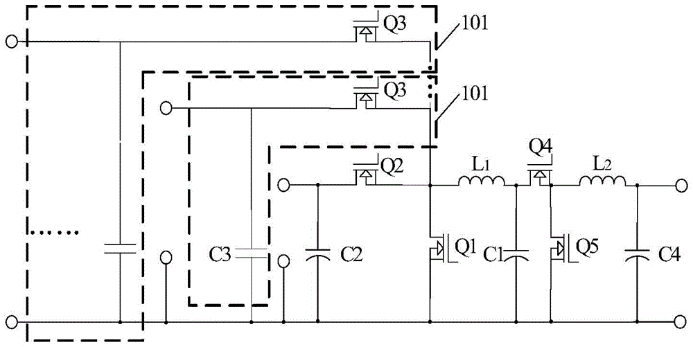
The invention provides a bidirectional DCDC converter and an optical storage system. When a low-voltage input / output interface is connected with energy storage equipment, the energy storage equipment can obtain high voltage from a high-voltage input / output interface through a second switching tube and a second capacitor or obtain lower high voltage from a lower high-voltage input / output interface through a third switching tube and a third capacitor, then, the energy storage equipment is charged after the voltage is reduced through a first switching tube, a first capacitor and a first inductor, at the moment, the system can enable the energy storage equipment to obtain electric energy through the lower high-voltage input / output interface with lower voltage reduction to achieve charging and reduce loss of the electric energy in the charging process. Similarly, the energy storage equipment can discharge through a high-voltage input / output interface with higher boosting to reduce loss of the electric energy in the discharging process. In addition, compared with traditional two sets of charging and discharging DCDC converters, the bidirectional DCDC converter has the advantages that the circuit cost is low, and high utilization rate of the electric energy of an overall distributed power supply system can be achieved.

Description

technical field [0001] The invention relates to the technical field of electric energy conversion, in particular to a bidirectional DC-DC converter and an optical storage system. Background technique [0002] The current situation of multiple new energy grid-connected power generation has brought a certain burden to the stability of the large power grid. In order to reduce the proportion of new energy grid-connected and increase its self-generation and self-use rate, the power supply system in the prior art mostly uses energy storage equipment and A distributed power supply system that combines a variety of new energy grid-connected power generation, because the energy storage equipment needs to be replaced manually, its configuration voltage is low, generally 48V, so its charging and discharging requires a DCDC converter with a high boost ratio. [0003] The two sets of charge-discharge DCDC converters or bidirectional DCDC converters traditionally used can make the energy ...

Claims


Application Information

Patent Timeline
Patent Type & Authority Patents(China)
IPC IPC(8): H02J3/32
CPCH02J3/32
Inventor 李跃超李姣丽胡兵李本强尹聪
Owner SUNGROW POWER SUPPLY CO LTD
Learn More