String Vibration Velocity Tester Using Vibration Motor as Wave Source and Its Operation Method

A vibration motor and experimental instrument technology, applied in the direction of instruments, educational tools, teaching models, etc., can solve the problems of experimental teaching quality influence, demonstration effect is not obvious, equipment structure is complex, etc., to achieve excellent experimental teaching quality, easy adjustment and measurement , the effect of high experimental precision

Inactive Publication Date: 2016-07-27
SHENYANG NORMAL UNIV
View PDF5 Cites 0 Cited by
  • Summary
  • Abstract
  • Description
  • Claims
  • Application Information

AI Technical Summary

Problems solved by technology

[0003] The purpose of the present invention is to solve the problems of existing string vibration experiment instruments and devices in different degrees, such as complicated equipment structure, high cost, blind spots in the experiment, low experiment efficiency, inconspicuous demonstration effect, high requirements on string materials, and poor reliability. Due to technical problems such as the impact of experimental teaching quality, a new type of string vibration velocimetry experiment instrument with vibration motor as the wave source is provided.

Method used


Image

  • String Vibration Velocity Tester Using Vibration Motor as Wave Source and Its Operation Method

Examples


Embodiment 1

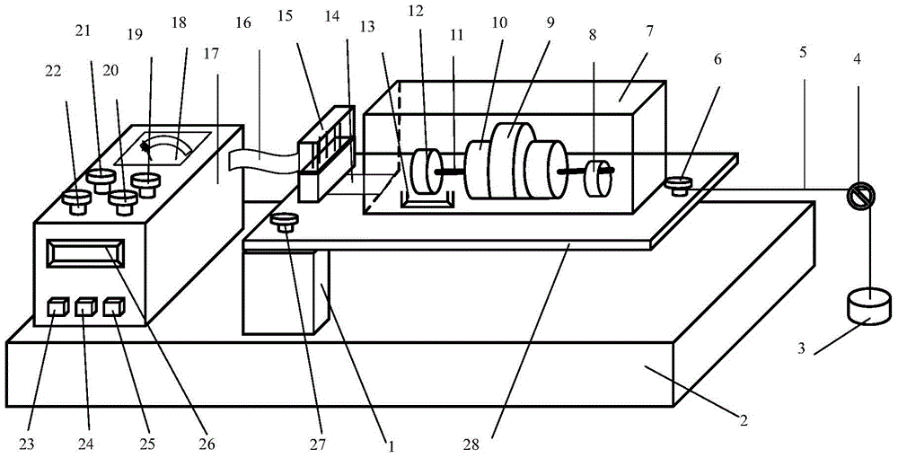
[0015] see figure 1 , the vibrating motor is the wave source of the string vibration speed test instrument, including the main body of the tester, the bottom of the main body of the tester is provided with a base 2, and the base 2 and the fixed plate 28 are supported and fixed by the support column 1. The main body of the experimenter is equipped with a vibration motor part 7 , and the vibration motor part 7 is installed above the fixed plate 28 . Above-mentioned column 1 single-point supports and fixes flat plate 28 and is fixed with screw 27. A vibration motor 10 is installed in the vibration motor part 7 , and the vibration motor 10 is fixed on a fixed plate 28 by a vibration motor fixing frame 9 . On the right side of the outer rotating shaft 11 of the vibration motor 10, an eccentric block 8 is installed; The lead wire 14 of the vibration motor 10 is connected to one end of the terminal 15; A DC power supply speedometer 17 is installed on the left side of the base 2, a...


PUM


Abstract

The invention provides a string vibration speed measurement experiment instrument with a vibration motor as a wave source. The string vibration speed measurement experiment instrument with the vibration motor as the wave source aims to solve the technical problems that according to an existing string vibration experiment instrument, an equipment structure is complicated, manufacturing cost is high, a dead zone exists during an experiment, the experiment efficiency is low, and the demonstration effect is poor. The string vibration speed measurement experiment instrument comprises an experiment instrument body. A base is arranged at the bottom of the experiment instrument body, and a vibration motor assembly is installed on the experiment instrument body. The vibration motor assembly is installed on a supporting stand column through a fixing flat plate. The vibration motor is installed in the vibration motor assembly. An eccentric block is installed on the right side of an outer rotating shaft of the vibration motor. A speed measurement disk and a photoelectric door are installed on the left side of the outer rotating shaft of the vibration motor. A direct-current power source speed measurement instrument is installed on the right side of the base. A voltage adjusting and frequency adjusting power source and a motor speed measurement instrument are installed on the direct-current power source speed measurement instrument. The voltage adjusting and frequency adjusting power source is provided with a voltage adjustment and frequency adjustment alternation switch, a power switch and the like. The motor speed measurement instrument is provided with a power supply switch, a frequency switch and the like. When the string vibration speed measurement experiment instrument is used, through the steps of power source connection, voltage adjustment and the like, the string vibration frequency is obtained by measuring the vibration frequency with the vibration motor as the wave source finally. According to the string vibration speed measurement experiment instrument with the vibration motor as the wave source, the structure is reasonable, and an operation method is easy to grasp.

Description

technical field [0001] The invention relates to a string vibration tester, in particular to a string vibration speed measurement tester with a vibration motor as a wave source. The string vibration experiment instrument is mainly used in the physics experiment of the university, and belongs to the technical field of mechanical heat physics experiment. Background technique [0002] At present, in the field of mechanothermal physics string vibration experiments, the following vibration modes of string vibration wave sources are generally adopted: the string vibration mode with the electric vibration tuning fork as the wave source or the string vibration mode with the electromagnetic oscillator as the wave source. There are many disadvantages in the above methods. Although the first method has obvious demonstration effect and low cost, there are serious experimental blind spots and high experimental efficiency is low. The latter kind of demonstration effect is not obvious, and...

Claims


Application Information

Patent Timeline
Patent Type & Authority Patents(China)
IPC IPC(8): G09B23/06
CPCG09B23/06
Inventor 焦义
Owner SHENYANG NORMAL UNIV
Why Eureka
Try Eureka