
Backlight module and display device

A technology of backlight module and display device, which is applied in the direction of lighting device, cooling/heating device of lighting device, optics, etc., and can solve the problems of low light source, light decay service life, and unsatisfactory heat dissipation effect, etc.

Active Publication Date: 2015-01-28
BOE TECH GRP CO LTD
View PDF4 Cites 7 Cited by
  • Summary
  • Abstract
  • Description
  • Claims
  • Application Information

AI Technical Summary

Problems solved by technology

[0005] The technical problem to be solved by the present invention is to provide a backlight module and a display device to overcome the unsatisfactory heat dissipation effect caused by the use of an aluminum substrate to dissipate heat from the light source in the prior art, which is likely to cause serious light decay and low service life of the light source.

Method used


Image

  • Backlight module and display device
  • Backlight module and display device
  • Backlight module and display device

Examples


Embodiment Construction

[0023] The specific implementation manners of the present invention will be further described in detail below in conjunction with the accompanying drawings and embodiments. The following examples are used to illustrate the present invention, but are not intended to limit the scope of the present invention.

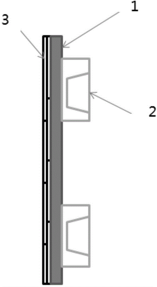
[0024] Such as figure 1 As shown, the present invention provides a backlight module, which includes:

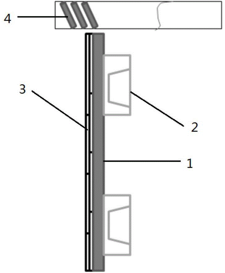
[0025] A PCB (Printed Circuit Board, printed circuit board) substrate 1 , a plurality of light source devices 2 are provided on one side of the PCB substrate 1 , and a graphite heat conducting layer 3 is provided on the other side of the PCB substrate 1 .

[0026] The graphite heat conduction layer is used to conduct heat conduction treatment for the heat in the fuselage, and the use of graphite's own characteristics makes its horizontal thermal conductivity as high as 1000w / mk. This heat conduction parameter can set the graphite heat conduction layer in the same directi...


PUM


Abstract

The invention relates to the technical field of display, in particular to a backlight module and a display device. The backlight module comprises a PCB (printed circuit board) substrate, a plurality of light source devices are arranged on one side of the PCB substrate, and the other side of the PCB substrate is provided with a graphite heat conduction layer. The backlight module and the display device have the advantages that heat in a machine body is conducted by means of the graphite heat conduction layer, heat conduction is realized by taking advantages of intrinsic special characteristics of graphite, the horizontal heat conductivity is up to 1000w / mk, the attachment direction of the graphite heat conduction layer is enabled to be identical to thermal air orientation direction for heat dissipation, and accordingly heat dissipation efficiency can be improved maximally, light attenuation is avoided, and service lives of light sources are prolonged.

Description

technical field [0001] The invention relates to the field of display technology, in particular to a backlight module and a display device. Background technique [0002] In the production process of liquid crystal displays, in order to better transfer the heat generated by the light source in the fuselage, aluminum substrates are usually used to dissipate heat. Let it out. [0003] In practical application, it is found that during the long-term use of the fuselage with this heat dissipation method, the heat dissipation efficiency of the aluminum substrate is relatively low, which causes the heat dissipation of the light source to be insufficient in time, resulting in the light source being in a high temperature state all the time, which in turn leads to serious light decay of the light source , thereby affecting the brightness and the service life of the light source, so that the display quality of the final product cannot be guaranteed. Contents of the invention [0004]...

Claims


Application Information

Patent Timeline
Patent Type & Authority Applications(China)
IPC IPC(8): G02F1/1333F21V29/85F21Y101/02
CPCF21Y2101/00G02F1/133385G02F1/1336G02F1/133628G02F1/133603G02F1/133608G02F1/133311G02F1/133514G02F1/133528G02F1/133553G02F1/1337G02F1/1339G02F2202/36G02F1/133548
Inventor 朱琳武延兵
Owner BOE TECH GRP CO LTD
Learn More