Adjusting method for vacuum ultraviolet plane grating dispersion spectrograph

A technology of vacuum ultraviolet light and planar grating, which is applied in the field of spectroscopy, can solve the problems of difficult and precise adjustment, decreased accuracy of installation and adjustment, and high cost of installation and adjustment, and achieve the effects of high precision, low cost, and less labor time consumption

Inactive Publication Date: 2015-01-28
CHANGCHUN INST OF OPTICS FINE MECHANICS & PHYSICS CHINESE ACAD OF SCI
View PDF5 Cites 3 Cited by
  • Summary
  • Abstract
  • Description
  • Claims
  • Application Information

AI Technical Summary

Problems solved by technology

[0004] In order to solve the problem that the vacuum ultraviolet planar grating spectrometer is difficult to be accurately installed and adjusted in the atmosphere, the installation cost is high, and the traditional method is easy to cause diffraction of the installed wavelength during the installation and adjustment, which leads to a serious decline in the installation and adjustment accuracy. It is suitable for the installation and adjustment method of the vacuum ultraviolet grating dispersive spectrometer, and realizes the high-precision adjustment ability of the vacuum ultraviolet grating spectrometer in the atmospheric visible light band, thereby saving the installation cost and improving the adjustment accuracy

Method used


Image

  • Adjusting method for vacuum ultraviolet plane grating dispersion spectrograph
  • Adjusting method for vacuum ultraviolet plane grating dispersion spectrograph
  • Adjusting method for vacuum ultraviolet plane grating dispersion spectrograph

Examples


Embodiment Construction

[0015] The implementation of the method of the present invention will be further described in detail below in conjunction with the accompanying drawings.

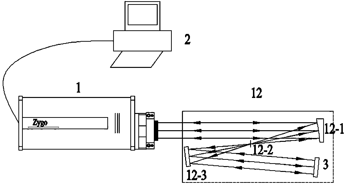
[0016] Such as figure 1 As shown, the vacuum ultraviolet grating 12 - 4 is replaced by a plane mirror 3 in the spectrometer 12 , and the spectrometer 12 is irradiated by the collimated light emitted by the Zygo interferometer 1 . First adjust the telescope 12-1 in the spectrometer 12, the slit 12-2 and the collimating mirror 12-3, so that the outgoing light of the collimating mirror 12-3 is a collimated light; then adjust the plane mirror 3 to follow the collimated light along the original optical path Return to Zygo Interferometer 1. The computer control processing system 2 is connected with the Zygo interferometer 1 to observe the wave aberration and fine-tune the front-end optical components, and obtain the optimal wave aberration image of the system through the computer control processing system 2 to complete the insta...


PUM


Abstract

The invention discloses an adjusting method for a vacuum ultraviolet plane grating dispersion spectrograph and belongs to the technical field of spectrographs. The adjusting method is used for solving the problem that precision is lowered when the vacuum ultraviolet grating spectrograph is adjusted. According to the adjusting method, an interferometer serves as the light source, a plane mirror is used for replacing a vacuum ultraviolet grating in an original light path, and a system wave aberration interferogram is used for sequentially adjusting a telescoping system, a collimation system and a slot of the spectrograph; afterwards, a visible light grating is used for replacing the plane mirror, collimation light of a parallel mercury lamp characteristic spectrum built through a mercury lamp and the collimation system serves as the adjusting light source, an image surface ideal spectrum chart of the system under the vacuum ultraviolet waveband is calculated, the vacuum ultraviolet wavelength corresponding to the mercury lamp characteristic spectrum is calculated according to the groove density of the visible light grating for replacement and the vacuum ultraviolet grating of the vacuum ultraviolet spectrograph to be adjusted, the positions of all vacuum ultraviolet spectrum lines corresponding to the mercury lamp characteristic spectrum on an image surface are recorded, the light grating and a focusing mirror are adjusted in sequence, and the positions of mercury lamp characteristic spectrum lines fall on the optimal positions obtained through calculation.

Description

technical field [0001] The invention relates to a method for installing and adjusting a vacuum ultraviolet plane grating dispersion spectrometer, which belongs to the field of spectrum technology. Background technique [0002] Vacuum ultraviolet planar grating spectrometer plays an indispensable role in the field of atmospheric remote sensing, spectral analysis and performance testing of standard far ultraviolet light sources. But for the vacuum ultraviolet grating spectrometer, since the radiation in the vacuum ultraviolet band is completely absorbed in the atmosphere, it cannot be installed and adjusted under the condition of visible light environment, and when the spectral bandwidth requires very high precision, small adjustment errors will be The performance of the spectrometer is greatly affected, so the difficulty and complexity of the installation and adjustment have brought great difficulties to the integrated application of the vacuum ultraviolet grating spectromete...

Claims


Application Information

Patent Timeline
IPC IPC(8): G01J3/28
Inventor 王淑荣于磊林冠宇
Owner CHANGCHUN INST OF OPTICS FINE MECHANICS & PHYSICS CHINESE ACAD OF SCI
Why Eureka
Try Eureka