
Liquid crystal display device and backlight module

A backlight module and backplane technology, which is applied in the direction of lighting devices, fixed lighting devices, lighting device components, etc., can solve problems such as unfavorable thin design of display devices, and achieve the effect of being conducive to thin design and realizing positioning

Active Publication Date: 2015-01-28
TCL CHINA STAR OPTOELECTRONICS TECH CO LTD
View PDF6 Cites 21 Cited by
  • Summary
  • Abstract
  • Description
  • Claims
  • Application Information

AI Technical Summary

Problems solved by technology

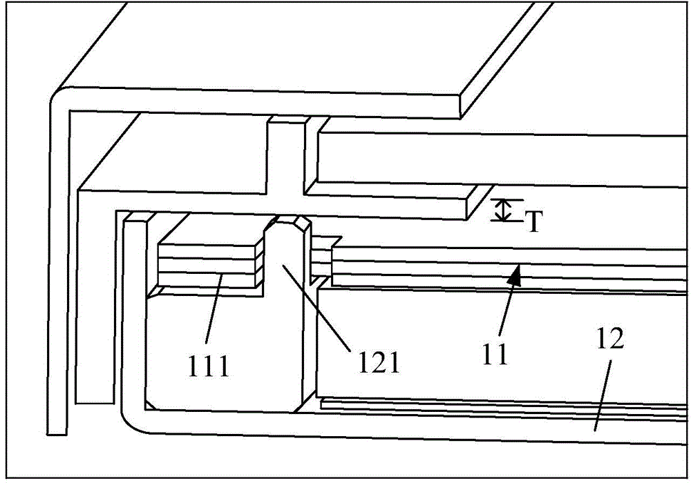
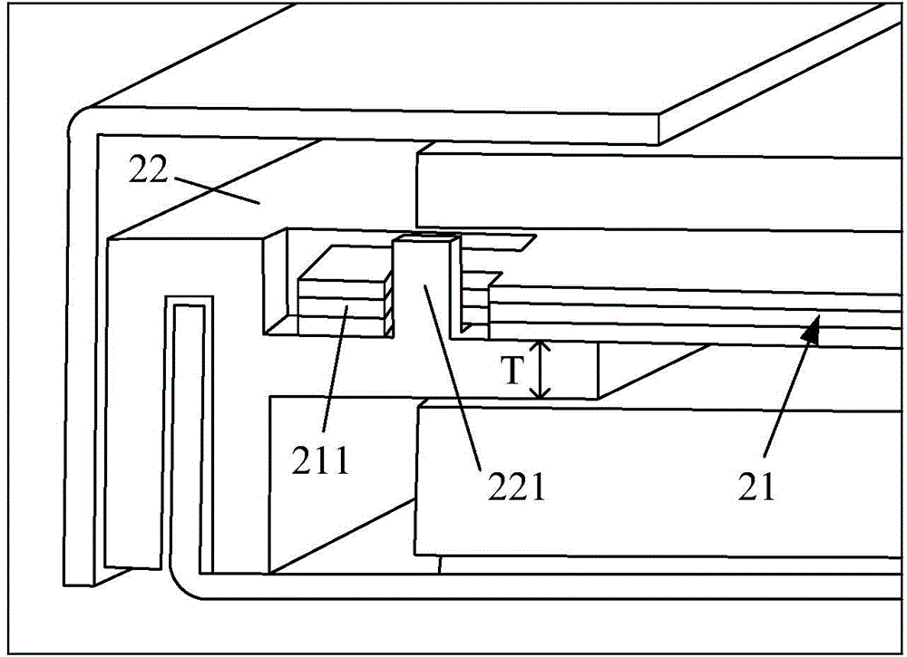
However, since the plastic frame carries the extension of the display panel and the optical film group is arranged up and down, in the thickness direction of the liquid crystal display device, there is inevitably a thickness T of the extension part of the plastic frame, which is not conducive to the development of the liquid crystal display device. Thin design

Method used


Image

  • Liquid crystal display device and backlight module
  • Liquid crystal display device and backlight module
  • Liquid crystal display device and backlight module

Examples


Embodiment Construction

[0022] The technical solutions in the embodiments of the present invention will be clearly and completely described below in conjunction with the accompanying drawings in the embodiments of the present invention. Obviously, the embodiments described below are only part of the embodiments of the present invention, not all of them. Example. Based on the embodiments of the present invention, all other embodiments obtained by persons of ordinary skill in the art without creative efforts fall within the protection scope of the present invention.

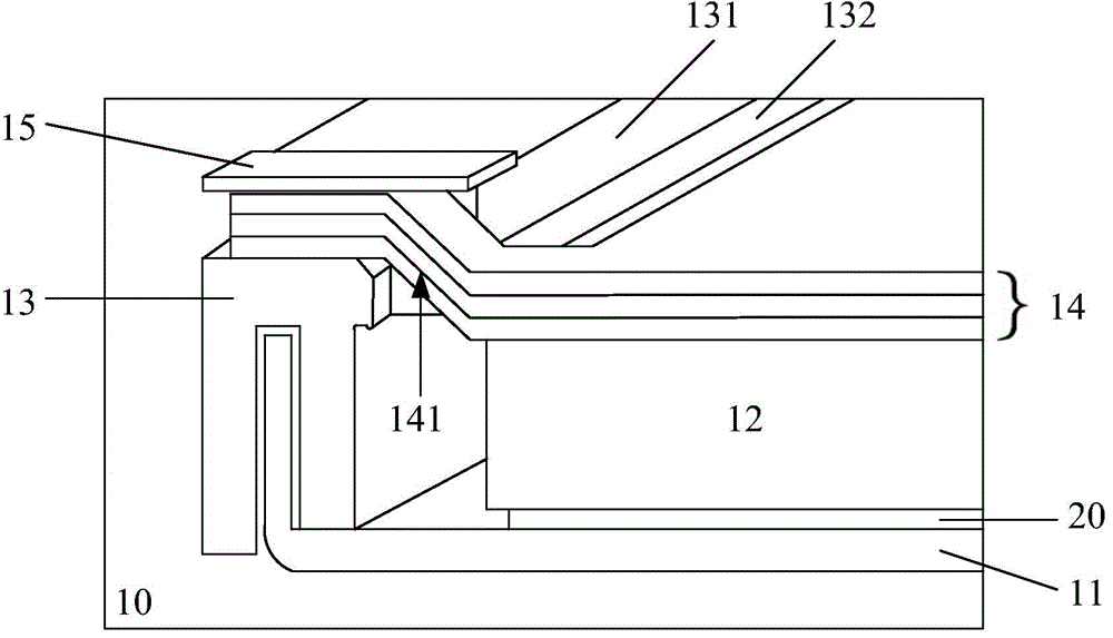
[0023] image 3 is a structural cross-sectional view of a backlight module in a preferred embodiment of the present invention, Figure 4 yes image 3 A partial exploded schematic diagram of the backlight module shown, Figure 5 yes image 3 A schematic diagram of the positioning of the optical film set of the backlight module shown. Please combine Figure 3 ~ Figure 5 As shown, the backlight module 10 of this embodiment at least inc...


PUM


Abstract

The invention provides a liquid crystal display device and a backlight module. An optical film group of the backlight module comprises at least one lug portion, each lug portion comprises a barb portion and an extension portion, and each barb portion extends towards a rubber frame from the edge of the optical film group. The rubber frame of the backlight module is provided with a first bearing portion and a second bearing portion, the first bearing portion and the second bearing portion extend towards a light guide plate, the first bearing portion is provided with a containing groove and a retaining portion, and the second bearing portion is used for bearing a display panel and enabling the display panel to be abutted against the first bearing portion. A first notch communicated with the containing groove is formed in the retaining portion, the extension portion is penetratingly arranged in the first notch, the barb portion is contained in the containing groove, and the retaining portion prevents the barb portion from moving towards the light guide plate. Thinning design of the liquid crystal display device is benefitted while positioning of the optical film group is realized.

Description

technical field [0001] The invention relates to the field of liquid crystal display technology, in particular to a liquid crystal display device and a backlight module thereof, which realize the positioning of an optical film group under a thin design. Background technique [0002] The backlight module of the liquid crystal display device mainly includes a light source, a plastic frame, a back plate, a light guide plate and an optical film group, wherein the light guide plate is arranged on the lower side of the plastic frame facing the back plate, and the optical film group is arranged on the upper side of the plastic frame. On the side, the light guide plate is used to convert the point light source into a surface light source to realize the display, and the optical film group is used to make the light uniform and improve the display brightness. [0003] The material of the optical diaphragm group itself is very soft and fragile. In order to prevent the optical diaphragm g...

Claims


Application Information

Patent Timeline
Patent Type & Authority Applications(China)
IPC IPC(8): F21S8/00F21V17/10G02F1/13357
CPCF21V17/10G02B6/0088G02F1/133608G02F1/133308G02F1/133317
Inventor 萧宇均阙成文
Owner TCL CHINA STAR OPTOELECTRONICS TECH CO LTD
Learn More