Eureka AIR delivers breakthrough ideas for toughest innovation challenges, trusted by R&D personnel around the world.

Bearing dismantling device

A bearing dismounting device and bearing technology, which is applied to hand-held tools, manufacturing tools, etc., can solve problems such as waste of resources, abnormal operation of bearings, and large vibration, so as to reduce repairs or replacements, shorten production cycles, and ensure safe use. Effect

Inactive Publication Date: 2015-01-28
HARBIN DONGAN ENGINE GRP
View PDF0 Cites 1 Cited by
  • Summary
  • Abstract
  • Description
  • Claims
  • Application Information

AI Technical Summary

Problems solved by technology

For tapered roller bearings, an interference fit is used between the outer ring and the bearing bush on the casing during design. Since the inner and outer rings of the tapered roller bearing can be disassembled, the inner ring is separated with the shaft when disassembled, and the outer ring remains in the machine. In the mounting hole of the bearing bush on the box, it is necessary to apply force on the end face of the outer ring of the bearing to disassemble it separately. Since the outer ring of the bearing and the bush are in an interference fit, it is easy to drive the bush during the force application process, thereby deviating from the Its correct installation position exceeds the design requirements
For devices that require continuous use, abnormal bearings and large vibrations are likely to occur during continuous use, which will affect the safety of use. Repairing or replacing new products will increase the cost and prolong the production cycle, resulting in unnecessary waste of resources.

Method used


Image

  • Bearing dismantling device
  • Bearing dismantling device

Examples


Embodiment Construction

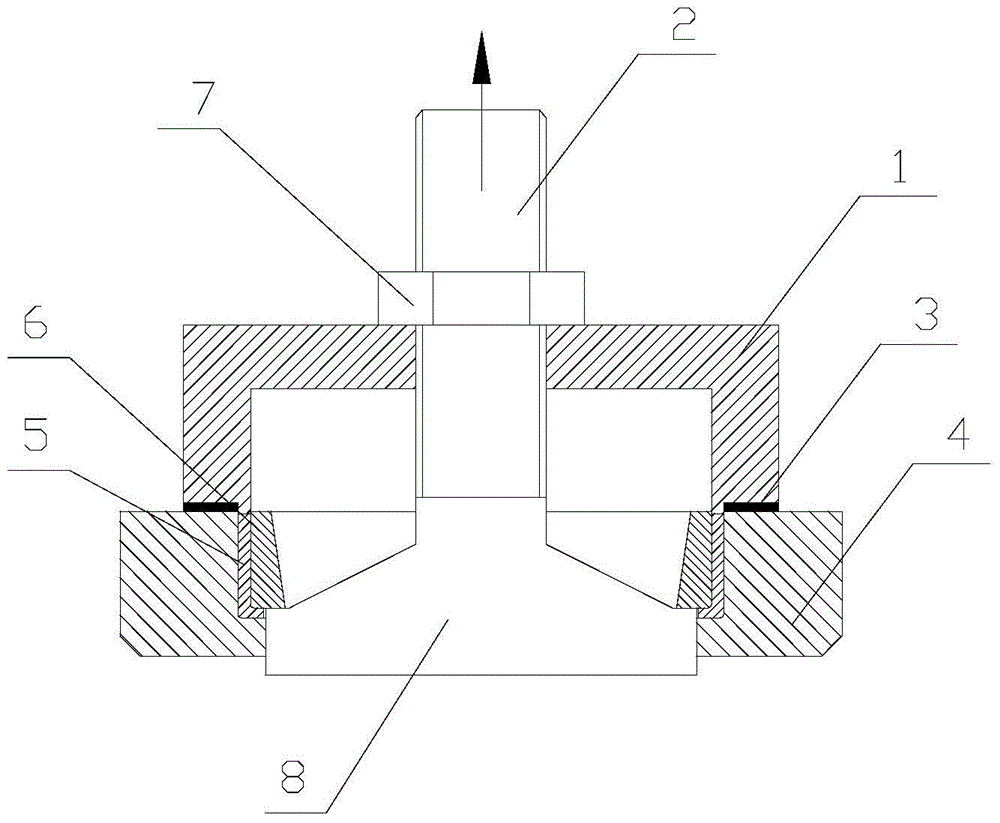
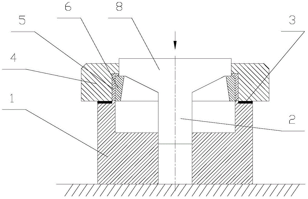
[0008] As shown in the figure, the bearing removal device includes a pull rod 2, a pressure ring 1, and an adjustment pad 3. The pressure ring 1 is fixed in the direction in which the bearing outer ring 6 is disassembled, and is in the shape of a round cup. The end face of the part 4 of the bush is matched, and the end face of the pressure ring 1 is also provided with a protruding step, and the step is matched with the end face of the bearing bush 5. greater than the width of the bearing outer ring 6; the tie rod 2 and the bottom of the pressure ring 1 have a gap fit, and one end is designed with a disc 8, the end face of the disc 8 can be in contact with the end face of the bearing outer ring 6, and can follow the pull rod 2 Move in the direction of disassembly; the pull rod 2 passes through the bottom of the pressure ring 1, and the nut 7 is installed through the thread. As another method of the present invention, the bottom of the pressure ring 1 is placed on a fixed plane,...


PUM


Abstract

The invention relates to a bearing dismantling device, comprising a pull rod, a press ring and a regulating pad; the press ring is fixedly arranged in the dismantling direction of a bearing outer ring, the end surface of the press ring is matched with the that of a part provided with a bearing bush, a step arranged on the press ring is matched with the end surface of the bearing bush, the pull rod is in clearance fit with the bottom of the press ring, a disc is arranged at one end of the pull rod, the end surface of the disc is in contact with the end surface of the bearing outer ring and can move toward the dismantling direction along with the pull rod. The axial limiting of the bearing bush and the part provided with the bush during the disassembling of the bearing outer ring is realized, the bearing bush is prevented from being separated under the action of a disassembling force, the use safety is ensured, unnecessary repair or cost loss caused by replacement of a new product is reduced, and the production period is shortened.

Description

technical field [0001] The invention relates to a dismantling device, in particular to a bearing dismantling device. Background technique [0002] Bearings are widely used rotating components in mechanical transmission, and are generally installed between the shaft and the bearing bush on the casing. For tapered roller bearings, an interference fit is used between the outer ring and the bearing bush on the casing during design. Since the inner and outer rings of the tapered roller bearing can be separated, the inner ring is separated with the shaft when disassembled, and the outer ring remains in the machine. In the mounting hole of the bearing bush on the box, it is necessary to apply force on the end face of the outer ring of the bearing for separate decomposition. Since the outer ring of the bearing and the bush are in an interference fit, it is easy to drive the bush during the force application process, thereby deviating from the Its correct installation position excee...

Claims


Application Information

Patent Timeline
Patent Type & Authority Applications(China)
IPC IPC(8): B25B27/06
CPCB25B27/06
Inventor 徐秀波胡克伟李宏冯磊周丽芳李远于伟齐晓辉张羽徐童童
Owner HARBIN DONGAN ENGINE GRP
Why Eureka
Eureka Blog
Learn More