
Simple self-adaptation dummy-load circuit

A false load, self-adaptive technology, applied in the direction of electrical components, output power conversion devices, etc.

Active Publication Date: 2015-01-21
SHENZHEN ACAD OF AEROSPACE TECH
View PDF7 Cites 15 Cited by
  • Summary
  • Abstract
  • Description
  • Claims
  • Application Information

AI Technical Summary

Problems solved by technology

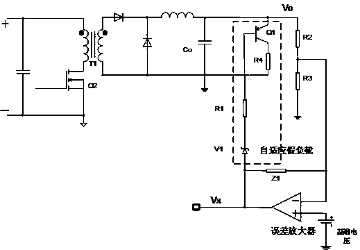
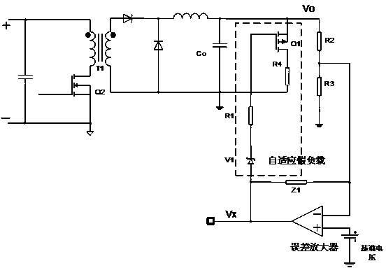
[0006] In order to solve the problems in the prior art that the dummy load circuit has no self-adaptive characteristics, many devices and low precision, the present invention proposes a dummy load circuit, Utilizing the existing voltage detection and compensation circuit in the power supply, two variables, the output voltage and the output voltage of the feedback compensator, are introduced into the detection unit circuit at the same time, so it only needs to add four additional devices to achieve a high degree of adaptability The dynamic preload circuit of the

Method used


Image

  • Simple self-adaptation dummy-load circuit
  • Simple self-adaptation dummy-load circuit
  • Simple self-adaptation dummy-load circuit

Examples


Embodiment Construction

[0021] The present invention will be further described below in conjunction with the accompanying drawings and specific embodiments.

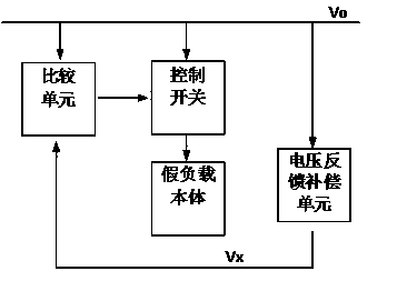
[0022] as attached figure 1 , the adaptive dummy load circuit of the present invention includes a voltage feedback compensation unit of the power supply itself, a comparison unit, a dummy load body and a control switch.

[0023] The voltage feedback compensation unit of the power supply itself detects the output voltage value, compares and compensates with the reference value through the operational amplifier, and outputs a voltage signal. This voltage signal can reflect the change of the output voltage, and is usually used to compare with the carrier signal to generate a PWM signal that controls the output of the power supply to stabilize. In the present invention, the voltage signal generated by the operational amplifier is used to compare with the output voltage. There is a comparison unit between them, if the difference between the two e...


PUM


Abstract

The invention provides a dummy-load circuit which aims at solving the problems that a dummy-load circuit in the prior art does not have the self-adaptation characteristic and is large in device number and low in accuracy. By means of the dummy-load circuit, a voltage detecting and compensating circuit existing in a power source is used, the two variables including the output voltage and the output voltage of a feedback compensation device are introduced in a detection unit circuit at the same time, and therefore the dynamic dummy-load circuit with the high self-adaptation degree can be achieved only by additionally arranging four devices.

Description

technical field [0001] The invention relates to a dynamic dummy load, in particular to a dummy load with simple circuit structure and self-adaptive operation. [0002] Background technique [0003] Since the development of switching power supplies, there are many control methods, such as the most commonly used PWM (Pulse Width Modulation), PFM (Pulse Frequency Modulation), and PAM (Pulse Amplitude Modulation). There are different circuit realization forms for each control method. Generally speaking, for switching power supplies, it is hoped that when the output load can be changed arbitrarily between no-load and rated load, the output of the power supply can achieve a high degree of stability (usually 1%). However, such requirements are sometimes difficult to meet. From the point of view of the control method, for the PWM control method, some circuits will limit a minimum duty cycle in order to keep the switching frequency constant. This minimum duty cycle tends to cause...

Claims


Application Information

Patent Timeline
Patent Type & Authority Applications(China)
IPC IPC(8): H02M1/32
CPCH02M1/32H02M1/0009H02M1/0016
Inventor 佟强刘安涛王晨
Owner SHENZHEN ACAD OF AEROSPACE TECH
Learn More