Bracket for liquid accumulator of air conditioner compressor
A technology of air-conditioning compressor and liquid accumulator, which is applied in refrigerators, refrigeration and liquefaction, lighting and heating equipment, etc., can solve the problems of affecting the working effect, reducing the gas-liquid separation effect, and liquid atomization, etc. The effect of reducing fogging and low impact force
- Summary
- Abstract
- Description
- Claims
- Application Information
AI Technical Summary
Problems solved by technology
Method used
Image
Examples
Embodiment approach 1
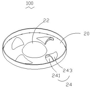
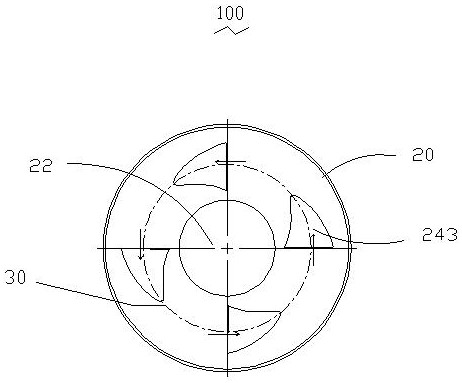
[0016] See Figure 1 to Figure 3 , A bracket 100 for an accumulator of an air conditioner compressor according to Embodiment 1 of the present invention includes a disc-shaped body 20 , a protrusion 22 , and stamped separation channels 24 distributed around the protrusion 22 . The protrusion 22 is roughly arched and formed in the central part of the body 20 . The separation channel 24 is a half cone separated along the generatrix, and its exit direction is tangential to the concentric circle 30 of the outer cylinder of the body 20 . The separation channels 24 are evenly distributed around the protrusion 22 on the body 20 according to a certain circumferential angle. Each separation channel 24 includes a flow guide part 241 and a flow guide part 243 covered on the flow guide part 241, wherein the flow guide part 241 is a channel through which the refrigerant can pass; Lead out in a certain direction. In this embodiment, the separation channel 24 is perpendicular to the axis o...
Embodiment approach 2
[0018] See Figure 4 and Figure 5 , the bracket 300 of an air conditioner compressor liquid accumulator in Embodiment 2 of the present invention is similar to the bracket 100 of an air conditioner compressor liquid accumulator in Embodiment 1, the difference is that an air conditioner compressor in this embodiment The support 300 of the liquid reservoir is provided with a rectangular baffle plate 36 on the mouth of the separation flow channel 34. The baffle plate 36 can press the filter screen and be welded and fixed. The baffle plate 36 cooperates with the separation flow channel 34 to form a section of closed flow channel. To guide the flow of gas-liquid mixture well.
Embodiment approach 3
[0020] See Figure 6 and Figure 7 , the bracket 400 of an air conditioner compressor accumulator in the third embodiment of the present invention is similar to the first embodiment, the difference is that the separation flow channel 44 in this embodiment includes an upper flow channel 44a and a lower flow channel 44b, wherein the upper flow channel 44a The protrusion is formed above the body 40, and the lower flow channel 44b is formed below the body 40, and the upper flow channel 44a is opposite to the flow opening of the lower flow channel 44b, so that the upper flow channel 44a and the lower flow channel 44b are symmetrical on the upper and lower centers of the main body 40, respectively. . This structure can make the liquid flow rotate more fully and improve the effect of gas-liquid separation. It can be understood that this structure of symmetrically distributing the double-layer separation channels 44 on the upper and lower sides of the main body 40 can also be used i...
PUM
 Abstract
Description
Claims
Application Information
 - R&D
- Intellectual Property
- Life Sciences
- Materials
- Tech Scout
- Unparalleled Data Quality
- Higher Quality Content
- 60% Fewer Hallucinations
Browse by: Latest US Patents, China's latest patents, Technical Efficacy Thesaurus, Application Domain, Technology Topic, Popular Technical Reports.
© 2025 PatSnap. All rights reserved.Legal|Privacy policy|Modern Slavery Act Transparency Statement|Sitemap|About US| Contact US: help@patsnap.com


