Monitoring method of annulus displacement efficiency in simulated cementing engineering

A technology for displacement efficiency and wellbore simulation, which is applied in the directions of measurement, earthwork drilling, wellbore/well components, etc. It can solve the problems of large experimental error, poor versatility, and long experimental time, and achieve accurate and reliable displacement efficiency. The effect of strong applicability and field applicability

Active Publication Date: 2017-05-10
BC P INC CHINA NAT PETROLEUM CORP +1
View PDF1 Cites 0 Cited by
  • Summary
  • Abstract
  • Description
  • Claims
  • Application Information

AI Technical Summary

Problems solved by technology

However, at present, in the cementing engineering annular multiphase flow test, there are many methods for monitoring the displacement efficiency at home and abroad, but they all have obvious shortcomings: the waiting coagulation section method needs to wait for the cement slurry in the annular space to solidify and then cut the wellbore , observing the distribution of cement in the annular space to infer the displacement efficiency, but this method is complex to operate, takes a long time to experiment, and cannot measure the displacement efficiency in the flow, which is not conducive to in-depth research; the laser velocimetry method can monitor the real multiphase flow in the annular space Flow state, measuring displacement efficiency, but because the measurement liquid is required to have good light transmission, it is impossible to measure real cement slurry and other on-site experiments with slurry, resulting in a large gap between the experimental results and the actual site; the temperature measurement method can measure real cement The flow of slurry, drilling fluid, etc. in the annular space, but the temperature sensor needs to be immersed in the annular flow field during the measurement, so it will interfere with the flow field and affect the experimental results. In addition, the heat loss during the flow process is large, and the experimental error is large.
[0004] To sum up, the existing methods for monitoring the displacement efficiency of the annulus in simulated cementing engineering have obvious defects, and cannot accurately measure the displacement flow process of real cement slurry and drilling fluid in the annulus. Simulation and research needs

Method used


Image

  • Monitoring method of annulus displacement efficiency in simulated cementing engineering

Examples


Embodiment 1

[0029] A method for monitoring displacement efficiency of annulus in simulated cementing engineering, comprising the following steps:

[0030] a. Inject the displaced fluid and the displacement fluid with different conductivity into the annular space of the measurement section of the simulated wellbore respectively, wherein the conductivity of the displaced fluid is C 1 , the conductivity of the displacement fluid is C 2 ;

[0031] b. Send excitation current to the annular space of the measurement section, establish a sensitive field in the annular space area of ​​the simulated wellbore measurement section, and collect voltage signals;

[0032] c. The conductivity information of each point in the sensitive field is obtained by calculating the voltage signal, so that the conductivity at different periods is C 1 of the displaced fluid and a conductivity of C 2 The respective volumes occupied by the displacement fluids in the annular space of the simulated wellbore measurement...

Embodiment 2

[0046]This embodiment further illustrates the present invention in conjunction with the accompanying drawings. The present invention comprises the following steps:

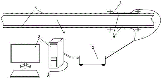
[0047] 1) The ERT system including the electrode sensor group 1, the electrical resistance tomography host 2 and the computer 3 is used as the measurement equipment. The electrode sensor group 1 of the ERT system is arranged in the measurement section of the simulated wellbore. It is required that the electrode sensor group 1 and the outside of the simulated wellbore The pipes 5 are connected by flanges, and the inner pipe 4 of the simulated wellbore is located in the outer pipe 5 of the simulated wellbore;

[0048] 2) Inject the displaced fluid (drilling fluid, etc.) and displacement fluid (spacer fluid or cement slurry, etc.) into the annular space of the measurement section formed by the simulated wellbore inner pipe 4, the simulated wellbore outer pipe 5, and the electrode sensor group 1, respectively, wherein...


PUM


Abstract

The invention discloses a method for monitoring the annular space displacement efficiency of simulated cementing engineering. The method includes respectively injecting displaced liquid and displacing liquid with different electric conductivities into annular spaces of measurement sections of simulated pit shafts; creating sensitivity fields in regions of the annular spaces of the measurement sections of the simulated pit shafts and acquiring voltage signals; computing information of electric conductivities of various points in the sensitivity fields to obtain the occupied volumes of the displaced liquid with the electric conductivities C1 and the displacing liquid with the electric conductivities C2 in the annular spaces of the measurement sections of the simulated pit shafts in different periods; acquiring the displacement efficiency of the displacing liquid for the displaced liquid in a certain period according to the total volumes of the annular spaces of the measurement sections of the simulated pit shafts and the occupied volumes of the displacing liquid in the annular spaces of the measurement sections of the simulated pit shafts in the different periods; drawing displacement efficiency curve graphs by the aid of the acquired displacement efficiency and comprehensively analyzing the displacement efficiency of the displacing liquid for the displaced liquid in the annular spaces of the integral simulated pit shafts. The occupied volumes of the displacing liquid in the annular spaces of the measurement sections of the simulated pit shafts in the different period are acquired by means of analysis and identification. The method has the advantage that displacement flowing conditions of real cementing liquid in annular spaces can be effectively monitored by the aid of the method.

Description

technical field [0001] The invention relates to an efficiency monitoring method, in particular to a monitoring method for annulus displacement efficiency of simulated cementing engineering. Background technique [0002] Cementing engineering is a systematic project that inserts casing into the well and injects cement into the annular space between the wellbore and the casing or between the casing and the casing. The main purpose is to achieve good interlayer isolation and fix the casing. The cementing operation needs to inject flushing fluid, spacer fluid, cement slurry and other fluids into the annular space, which is a complex multiphase flow displacement process. Due to various reasons such as the complexity of drilling fluid, the replacement efficiency of drilling fluid in the annular space during the cementing process is greatly reduced, resulting in low replacement efficiency of cement slurry in the annular space, serious drilling fluid channeling, and poor interface c...

Claims


Application Information

Patent Timeline
Patent Type & Authority Patents(China)
IPC IPC(8): E21B33/13E21B47/00
CPCE21B33/13E21B47/005
Inventor 冯予淇曾凡坤冯彬马思平刘洋刘世彬范成友范伟华聂世均赵常青鲜明
Owner BC P INC CHINA NAT PETROLEUM CORP
Why Eureka
Try Eureka