
Elevator equipment

A technology for elevators and equipment, which is applied in the field of elevator equipment with a stop detection device, can solve the problems of limited installation space, cumbersome installation operations, and rising manufacturing costs, and achieve the effects of reducing manufacturing costs and simplifying installation and adjustment operations

Active Publication Date: 2015-01-21
HITACHI LTD
View PDF7 Cites 3 Cited by
  • Summary
  • Abstract
  • Description
  • Claims
  • Application Information

AI Technical Summary

Problems solved by technology

[0017] In the elevator equipment having the above-mentioned structure, it is necessary to provide the limit switch bracket 12, the limit switch 9, the limit cam 11, etc. for constituting the limit switch mechanism, so there is a problem that the manufacturing cost will increase.
In addition, in order to install the limit switch bracket 12 and the limit switch 9, etc., it is necessary to reserve the space required for installation, so when installing other equipment such as the safety device 15, the control device 16, and the tail cable 18, the existing installation space will be affected. limit problem
[0018] In addition, in the parking detection device of the elevator equipment, it is necessary to install the detection plate support 23 (and sometimes the limit switch support 12) for constituting the parking detection device. There is a problem that the installation work for each floor is very troublesome, including the alignment work of the installation position (height and flatness, etc.)

Method used


Image

  • Elevator equipment
  • Elevator equipment
  • Elevator equipment

Examples


Embodiment Construction

[0044] Hereinafter, embodiments of the present invention will be described in detail with reference to the drawings. The present invention is not limited to the following embodiments, and various modified examples and application examples of the technical concept of the present invention are also included in the scope of the present invention.

[0045] Next, a first embodiment of the present invention will be described. adopted with Figure 8 The same reference numerals indicate Figure 8 The same structural elements or structural elements having the same function, and their repeated descriptions are omitted here.

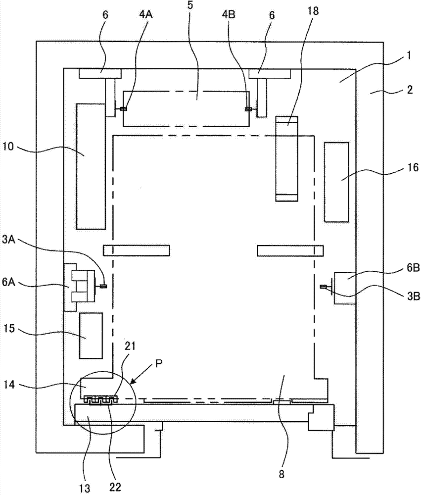
[0046] In this embodiment, the setting position of the parking detector in the lifting passage 1 is the same as Figure 8 The shown prior art elevator installation is different. Such as figure 1 As shown, the parking detector 21 provided on the elevator car 8 with a light-emitting part that emits light and a light-receiving part that receives light from the light-...


PUM


Abstract

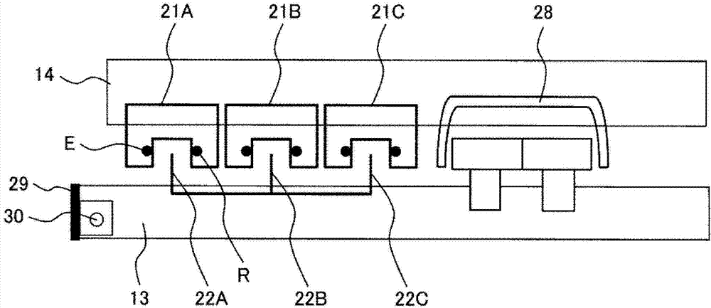
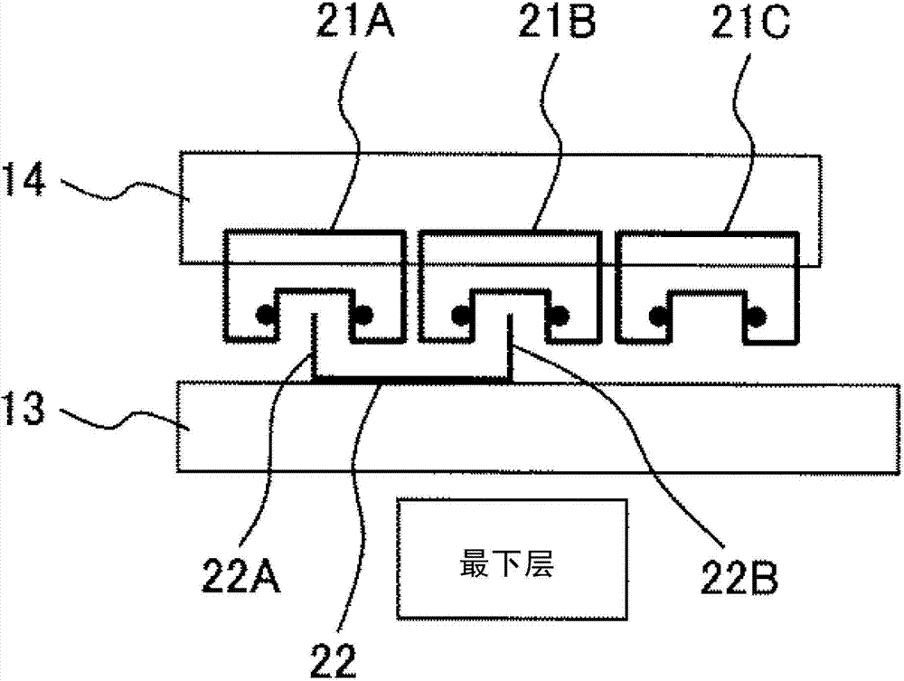
The invention provides elevator equipment without any mechanical room, but with a novel position exceeding prevention mechanism. The equipment at least prevents the elevating and lowering movements of an elevator car from exceeding specified positions when no position limiting switch is provided. The elevator car is provided with at least three unit stopping detectors each having a light emitting part and a light receiving part. Pairs of unit stopping detectors in different combinations are selected from the three unit stopping detectors for the lowermost floor, the common floors, and the uppermost floor respectively, and stopping detecting plates which block light between the light emitting parts and the light receiving parts of each selected pair of unit stopping detectors are arranged in elevating and lowering passages of elevator lobbies of the lowermost floor, the common floors, and the uppermost floor. In such a way, the lowermost floor, the common floors, and the uppermost floor can be determined according to the combinations of the unit stopping detectors. Therefore, the position limiting switch is not needed and the manufacture cost is lowered.

Description

technical field [0001] The invention relates to elevator equipment, in particular to an elevator equipment with a stop detection device. Background technique [0002] Elevator equipment usually consists of an elevator car, a counterweight, a main sling, a balance rope, and a tail cable. Furthermore, the elevator installation has a stop detection device which detects the stop positions of the elevator car at the individual floors. In the parking detection device, a parking detector having a light-emitting part that outputs light and a light-receiving part that receives the light is provided on the side of the elevator car, and a detection plate is provided at the parking position of the elevator car on each floor on the elevator passage side (hereinafter referred to as "stopping detection plate") detects the position of the elevator car (detection of a stop position) by blocking the light output from the stop detector with the stop detection plate. [0003] An elevator faci...

Claims


Application Information

Patent Timeline
Patent Type & Authority Applications(China)
IPC IPC(8): B66B1/36B66B5/00B66B11/02
CPCB66B1/36B66B5/00B66B11/02
Inventor 金山泰裕西野克典
Owner HITACHI LTD
Learn More