
A waterproof turnover box

A turnover box and box cover technology, used in rigid containers, locking equipment, closing and other directions, can solve the problems of items becoming wet and wet, and there is no waterproof measure at the joint of the box cover, and achieve the effect of enhancing the load-bearing capacity and being less prone to damage.

Active Publication Date: 2017-05-24
青岛冠宇工业设备有限公司
View PDF8 Cites 0 Cited by
  • Summary
  • Abstract
  • Description
  • Claims
  • Application Information

AI Technical Summary

Problems solved by technology

[0004] Therefore, the technical problem to be solved by the present invention is to overcome the zigzag turnover box in the prior art because there is no waterproof measure at the joint of the two box covers, which cannot prevent the water dripping on the box cover from flowing into the inside of the box through the above-mentioned joint so that Defects that cause the items stored in the box to become damp and wet, thus providing a waterproof turnover box that is durable, easy to stack, and has a good waterproof effect

Method used


Image

  • A waterproof turnover box
  • A waterproof turnover box
  • A waterproof turnover box

Examples


Embodiment 1

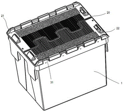
[0045] This embodiment provides a waterproof turnover box, such as Figure 1-6 As shown, a box body 1 comprising an upper opening, and a first box cover 21 and a second box cover 22 respectively rotatably connected to two opposite side walls of the box body 1, the first box cover 21 and the The second case cover 22 is respectively provided with several protruding teeth 31 and concave teeth 32 which can be buckled together when closed, and the lower surfaces of the first case cover 21 and the second case cover 22 are respectively provided with There are a first protruding band 41 and a second protruding band 42. The outwardly protruding bent part of the first protruding band 41 or the second protruding band 42 is closed at the upper end and opened at the lower end to form the protruding tooth 31. The upper end of the inwardly concave bent part of the belt 41 or the second convex belt 42 is open and the lower end is closed to form the concave tooth 32 , the open lower end of the...

Embodiment 2

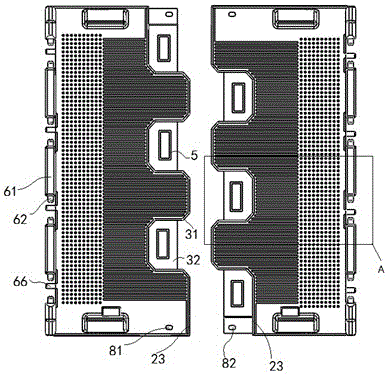
[0051] This embodiment provides a waterproof turnover box, which is an improvement on the basis of Embodiment 1, the difference is that waterproof measures are further added, such as Figure 7 and Figure 8 As shown, when the first case cover 21 and the second case cover 22 are snapped together, a first seam 20 is formed, and the first case cover 21 and the second case cover near the first seam 20 22 are respectively provided with a first blocking convex wall 23 that blocks water falling onto the upper surface of the box body 1 from flowing into the first seam 20 .

[0052] After the water drop falls on the upper surface of the box body 1, under the blocking effect of the above-mentioned first blocking convex wall 23, the water can be prevented from gathering at the position of the first seam 20, and the amount of water flowing to the position of the first seam 20 can be reduced, thereby reducing The waterproof pressure between the above-mentioned two adjacent outer surfaces ...

Embodiment 3

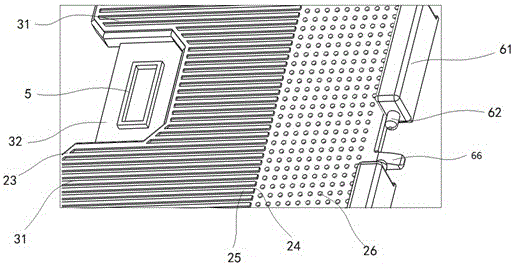
[0054] This embodiment provides a waterproof turnover box, which is an improvement on the basis of Embodiment 1 or 2, the difference is that a flow guide structure is added, such as figure 2 , image 3 , Figure 7 and Figure 8 As shown, a flow guide structure is also provided on the upper surface of the first case cover 21 and the second case cover 22; the flow guide structure includes several bars connected with the first blocking convex wall 23, and The elongated convex wall 25 of the diversion groove 24 is formed between any two adjacent ones.

[0055] The setting of elongated convex wall 25 can make there are less low-lying positions that can accommodate water on the first case cover 21 and the second case cover 22, and water is very easy to collect and flow out in the diversion groove 24, can reduce the second The amount of water stored on the upper surfaces of the first case cover 21 and the second case cover 22 reduces the risk of water leakage. Further, the long ...


PUM


Abstract

The invention provides a waterproof circulation box. The waterproof circulation box comprises a box body, a first box cover and a second box cover, wherein an opening is formed in the upper portion of the box body, and the first box cover and the second box cover are connected to the two opposite side walls of the box body in a rotatable mode respectively. The first box cover and the second box cover are each provided with a plurality of convex teeth and a plurality of concave teeth in a staggered mode, and the convex teeth can be connected with the concave teeth in a matched and buckled mode when the box covers are closed. The lower surface of the first box cover and the lower surface of the second box cover are provided with a first convex strip and a second convex strip respectively. The upper ends of the outwards-protruding bent portions of the first convex strip or the second convex strip are closed, the lower ends of the outwards-protruding bent portions of the first convex strip or the second convex strip are opened, and the convex teeth are formed; the upper ends of the inwards-sunken bent portions of the first convex strip or the second convex strip are opened, the lower ends of the inwards-sunken bent portions of the first convex strip or the second convex strip are closed, and the concave teeth are formed. The opened lower ends of the convex teeth are downwards attached to the closed lower ends of the concave teeth in a buckled mode from the opened upper ends of the concave teeth. The opened lower ends of the convex teeth are in contact with the closed lower ends of the concave teeth in an attached mode, water on the upper surface of the box body can be prevented from entering the interior of the box body along the first joint position formed after the first box cover and the second box cover are buckled, and therefore the waterproof effect can be achieved.

Description

technical field [0001] The invention relates to a waterproof turnover box, which belongs to the technical field of logistics storage equipment. Background technique [0002] With the continuous development of social economy, the logistics industry is developing rapidly. The two main activities of logistics are warehousing and transportation. The turnover box has been widely used in the fields of warehousing, transportation and even circulation processing because of its advantages of light weight, sturdiness and durability. application. The turnover box can be matched with a variety of logistics containers and workstations, and is used in warehouses, production sites and other occasions. Today, modern logistics management is increasingly valued by the majority of enterprises. The turnover box can complete the generalization of logistics containers. , Integrated management, which has increasingly become a must-have for production and distribution companies to carry out modern...

Claims


Application Information

Patent Timeline
Patent Type & Authority Patents(China)
IPC IPC(8): B65D43/16B65D55/02B65D21/02
CPCB65D21/0201B65D43/161B65D55/02
Inventor 单伟闫在明王田
Owner 青岛冠宇工业设备有限公司
Learn More