
Air conditioning device

An air conditioning and air conditioning technology, applied in the field of air conditioning devices, can solve the problems of complex configuration of indoor units, longer operation time, lower operation efficiency, etc., and achieve the effects of improving operation efficiency, ensuring comfort, and improving heat transfer force.

Active Publication Date: 2015-01-14
MITSUBISHI ELECTRIC CORP
View PDF9 Cites 2 Cited by
  • Summary
  • Abstract
  • Description
  • Claims
  • Application Information

AI Technical Summary

Problems solved by technology

[0012] In the air-conditioning devices described in the above-mentioned Patent Document 1 and the above-mentioned Patent Document 2, there are problems in that the arrangement of indoor units becomes complicated, the work efficiency in piping work and maintenance decreases, the work time becomes longer, and the construction cost becomes high.

Method used


Image

  • Air conditioning device
  • Air conditioning device
  • Air conditioning device

Examples


Embodiment approach 1

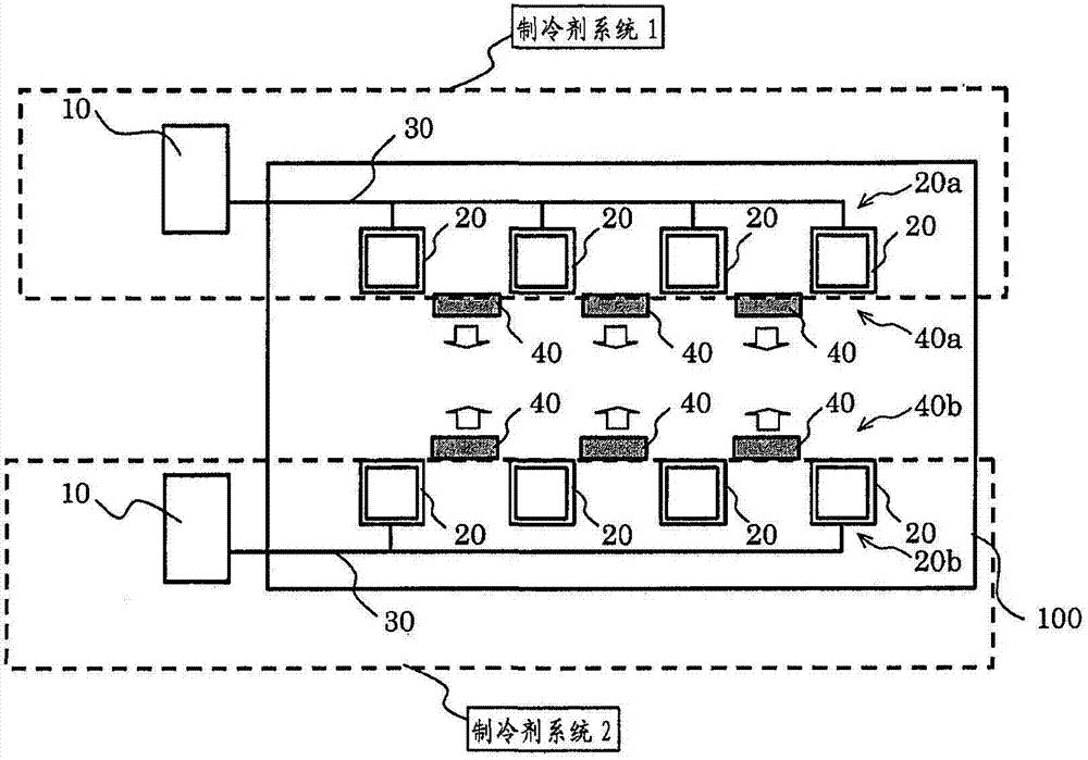
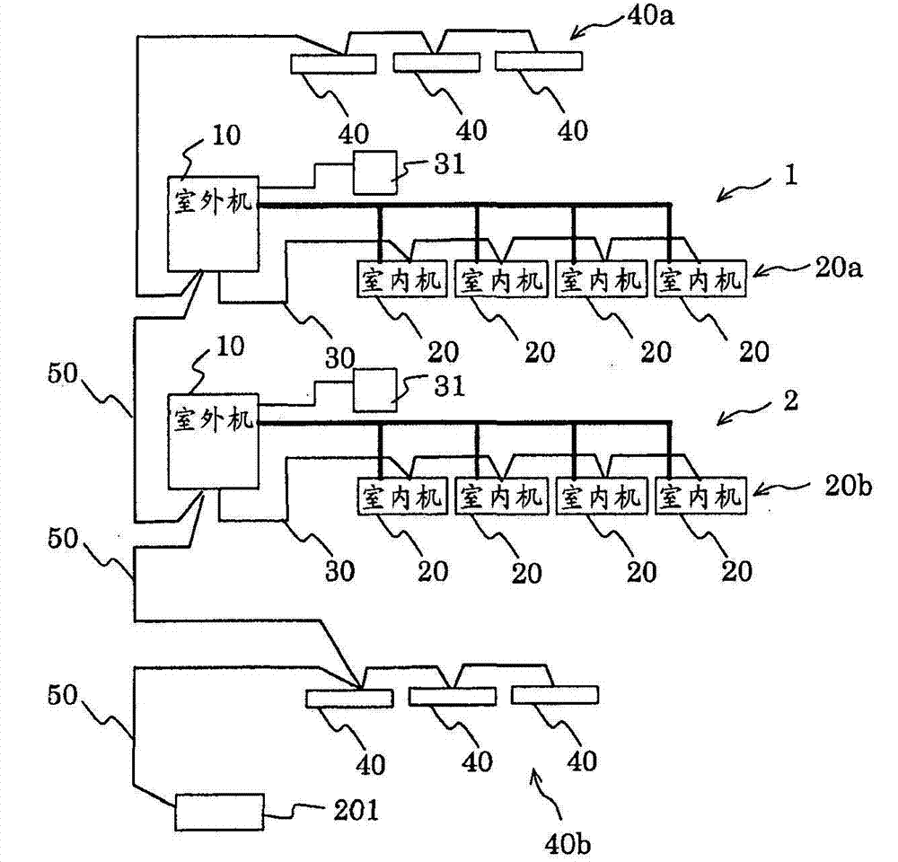
[0045] figure 1 It is the floor plan of the building to which the air-conditioning apparatus of Embodiment 1 of this invention was applied. figure 2 It is a figure which shows the connection structure of the air-conditioning apparatus concerning Embodiment 1 of this invention. exist figure 1 , figure 2 And in the figures mentioned later, what attached|subjected the same code|symbol is the same or corresponds to it, and it is common throughout the whole specification. Furthermore, the form of the component shown in the whole specification is an illustration only, and is not limited to these descriptions.

[0046] like figure 1 As shown, the air-conditioning apparatus includes a plurality (here, two) of refrigerant systems 1 and 2 as air-conditioning systems. The refrigerant systems 1 and 2 each include an outdoor unit 10 and an indoor unit 20 connected to the outdoor unit 10 by a refrigerant pipe 30 . In addition, here, four indoor units 20 are provided for each of the...

Embodiment approach 2

[0135] In Embodiment 1, the case where the system integration operation is applied to the air-conditioning apparatuses of two systems is described, but in Embodiment 2, the case of applying to the air-conditioning apparatuses of three systems is described. In addition, the modification applied to the same part as Embodiment 1 is also applicable to this Embodiment 2 similarly.

[0136] Figure 16 It is a floor plan of a building to which the air-conditioning apparatus according to Embodiment 2 of the present invention is applied.

[0137] The air-conditioning apparatus according to Embodiment 2 includes a refrigerant system 1 , a refrigerant system 2 , and a refrigerant system 3 , and air-conditioning of the same room 100 is performed by the three refrigerant systems. Each of the refrigerant systems 1 , 2 , and 3 includes an outdoor unit 10 and a plurality of indoor units 20 connected to refrigerant pipes 30 for the outdoor unit 10 . The air-conditioning apparatus further inc...


PUM


Abstract

An air conditioning device is provided with: refrigerant systems (1, 2) having an outdoor unit (10) and indoor units (20) and air conditioning the same room (100); and a circulator (40) for making temperature distribution in the room uniform. A load on each of the refrigerant systems (1, 2) being operated is determined, and when it is determined on the basis of the result of the determination of the loads that an increase in the operational efficiency can be expected, the air conditioning device is operated as follows: the operation of a refrigeration system which is determined as being subjected to a low load is stopped; integrated system operation is performed, the integrated system operation being that in which operation is integrated into a refrigeration system which is determined as being subjected to a high load; and discharge air which is blown from the indoor unit (20) of the refrigeration system which is determined as being subjected to a high load is conveyed by the circulator (40) to the air conditioning zone of the refrigeration system determined as being subjected to a low load.

Description

technical field [0001] The present invention relates to air conditioning devices. Background technique [0002] Conventionally, an air conditioner has been proposed that includes: a plurality of indoor units arranged in one air-conditioning target area; a plurality of outdoor units in which the indoor units are divided into a plurality of systems and provided for each system, and The system control unit operates according to the request from the indoor unit of the system; the system control unit controls the corresponding outdoor unit according to the request from the indoor unit belonging to each system; and the overall control unit controls a part of the system according to the operating load of each system. Pause (for example, refer to Patent Document 1). [0003] In this air-conditioning apparatus, by stopping the system operating at a low load, the air-conditioning load of each system can be increased, and the efficiency of the air-conditioning apparatus can be improve...

Claims


Application Information

Patent Timeline
Patent Type & Authority Applications(China)
IPC IPC(8): F24F11/02
CPCF24F2011/0046F24F3/065F24F11/89F24F2140/50
Inventor 滨田守亩崎史武菊地仁大西茂树有吉直人田村直道西宫一畅
Owner MITSUBISHI ELECTRIC CORP
Learn More