
Curved surface piezoelectric power generation cantilever beam

A piezoelectric power generation, cantilever beam technology, applied in the direction of generator/motor, piezoelectric effect/electrostrictive or magnetostrictive motor, electrical components, etc., can solve the problem that the cantilever beam system cannot be maintained under changing motion conditions Power generation efficiency, frequency constant, low, etc.

Inactive Publication Date: 2015-01-07
JILIN UNIV
View PDF6 Cites 7 Cited by
  • Summary
  • Abstract
  • Description
  • Claims
  • Application Information

AI Technical Summary

Problems solved by technology

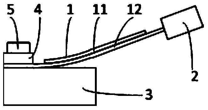
[0003] In order to solve the problem of low power generation efficiency caused by the constant natural frequency of the piezoelectric cantilever generator installed on the rotating mechanism and the inability to keep the cantilever system in a resonance state under changing motion conditions, a curved surface piezoelectric generator is proposed. Cantilever beam structure, the curved piezoelectric cantilever beam is composed of a curved piezoelectric vibrator, a free end mass block and a fixed support end, the fixed support end of the curved surface piezoelectric power generation cantilever beam structure is fixed on the mechanism for rotary motion, the system utilizes Rotary motion power generation, when the rotation speed changes, the curved surface piezoelectric vibrator contacts the fixed support end, the free length changes, the stiffness changes, and the resonance frequency of the system changes accordingly, so that it has a wider resonance frequency range, which can improve Piezoelectric power generation efficiency

Method used


Image

  • Curved surface piezoelectric power generation cantilever beam
  • Curved surface piezoelectric power generation cantilever beam
  • Curved surface piezoelectric power generation cantilever beam

Examples


Embodiment Construction

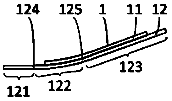
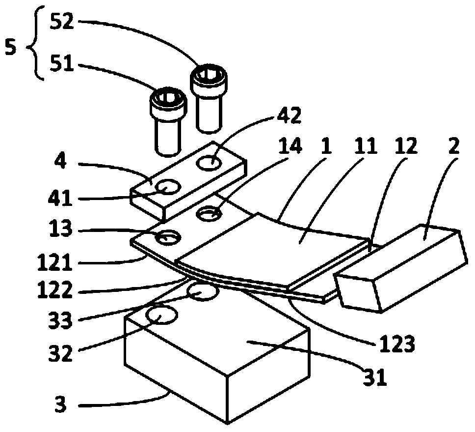
[0014] refer to figure 1 , figure 2 and image 3 , the curved piezoelectric power generation cantilever beam of the present invention is composed of a curved piezoelectric vibrator 1, a free end mass block 2, a fixed support end 3, a mounting gasket 4 and a bolt 5, wherein:

[0015] The curved piezoelectric vibrator 1 is connected in sequence by three parts with a smooth transition, which are the vibrator installation plane 121, the variable support curved surface 122 and the cantilever extension plane 123; one end of the curved piezoelectric vibrator 1 is arranged with a free-end mass block by bonding 2. The other end is fixed on the fixed support end 3, and fixed by the first bolt 51 and the second bolt 52 through the installation gasket 4; the variable support curved surface 122 intersects the vibrator installation plane 121 at the first intersection line 124, the The variable support curved surface 122 intersects the cantilever extension plane 123 at a second intersecti...


PUM


Abstract

The invention relates to a curved surface piezoelectric power generation cantilever beam. The cantilever beam comprises a curved surface piezoelectric vibrator, a free-end mass block, a fixed supporting end, a mounting pad and bolts, wherein the curved surface piezoelectric vibrator is formed by three parts, namely, a vibrator mounting plane, a changeable supporting curved surface and a cantilever stretching-out plane, which are sequentially connected and are in smooth transition, the cantilever stretching-out plane is connected with the free-end mass block, and the vibrator mounting plane is connected with the fixed supporting end by the bolts through the mounting pad and arranged on a rotating device to serve as a power generation device. The self-adaptation change of inherent frequency can be achieved according to the change of the rotating speed, so that the inherent frequency range of the power generation device is expanded, and accordingly the power generation amount is increased.

Description

technical field [0001] The invention belongs to the field of low-power power generation, and in particular relates to a curved piezoelectric power generation cantilever beam. Background technique [0002] Since the discovery of piezoelectric materials, their power generation characteristics have been widely used in various specific occasions, including strain test devices formed by converting stress into electrical energy, various ignition devices that directly generate instantaneous high voltage by impacting piezoelectric materials, and Electronic fuze devices, electronic power supply devices formed by bending piezoelectric cantilever beams formed by piezoelectric ceramics to supply various electronic devices, etc. The piezoelectric cantilever structure, as the simplest piezoelectric power generation structure, has been extensively studied and applied. The piezoelectric cantilever used for power generation generally has two working states, one is working at a non-resonant f...

Claims


Application Information

Patent Timeline
IPC IPC(8): H02N2/18
Inventor 吴越涂前进陈松杨志刚田晓超
Owner JILIN UNIV
Learn More