High Power Switch with Current Limiter

A high-power switch and current limiter technology, applied in high-voltage/high-current switches, electrical switches, high-voltage air circuit breakers, etc., can solve high technical risks and development costs, fail to achieve technical and economic effects, and break short-circuit current. Failure and other problems, to achieve the effect of shortening the arcing time, improving economic benefits, and improving the success rate of breaking

Active Publication Date: 2016-09-14
CHINA XD ELECTRIC CO LTD
View PDF5 Cites 0 Cited by
  • Summary
  • Abstract
  • Description
  • Claims
  • Application Information

AI Technical Summary

Problems solved by technology

When the peak value of the short-circuit current is very high, the strong current arc generated when the contacts in the arc extinguishing chamber are separated will burn the contacts. After the current crosses zero, the plasma between the contacts has a high concentration and temperature, causing the contacts to The thermal breakdown between them will cause the arc to re-ignite in the arc extinguishing chamber, resulting in failure to break the short-circuit current
If only by increasing the size of the arc extinguishing chamber or increasing the volume of the arc blowing chamber to improve the breaking capacity of the arc extinguishing chamber, it will increase the weight of the entire switch, increase the cost, and increase the burden on the operating mechanism, etc.
At the same time, for this type of switch, re-development of a new interrupter with a larger breaking capacity will bring high technical risks and development costs, and require a long development time. If the demand is not large, it will bring High cost pressure, unable to achieve good technical and economic results

Method used


Image

  • High Power Switch with Current Limiter
  • High Power Switch with Current Limiter
  • High Power Switch with Current Limiter

Examples


Embodiment Construction

[0025] The present invention will be described in further detail below in conjunction with the accompanying drawings:

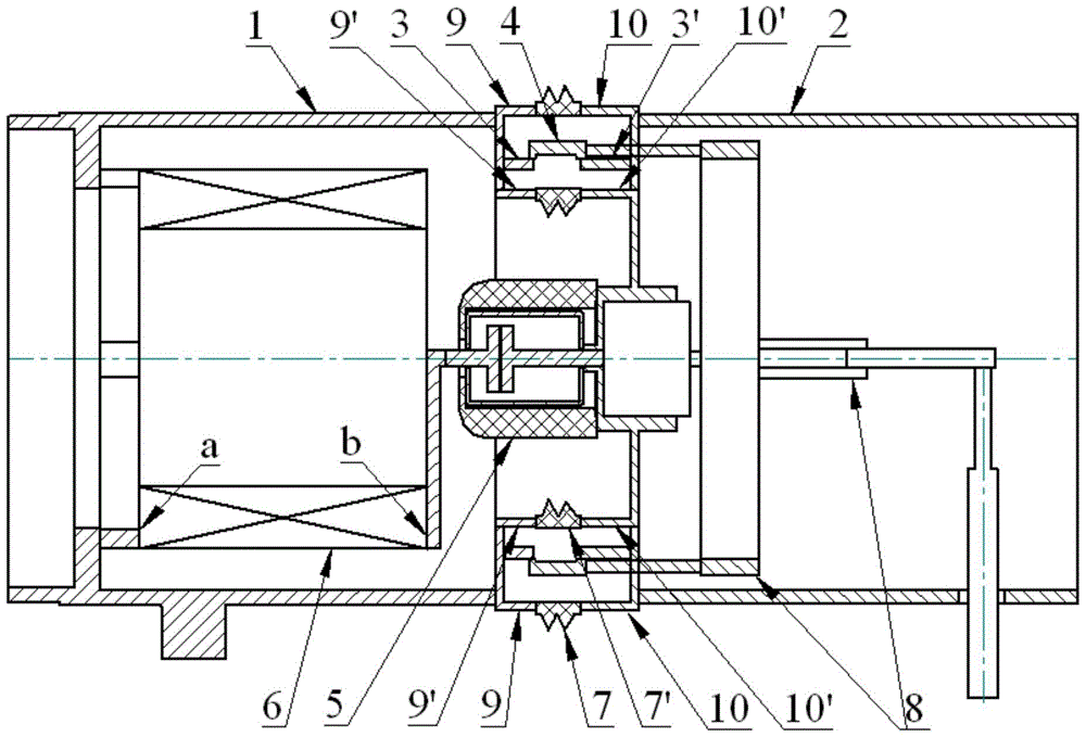
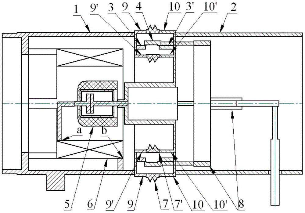
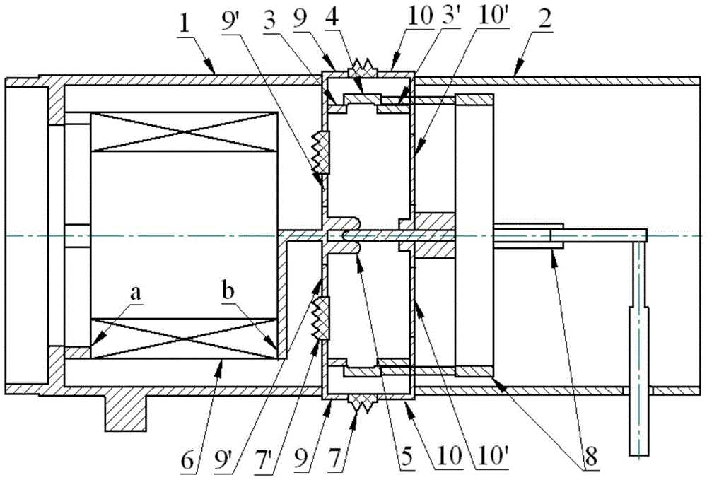
[0026] See figure 1 , figure 2 with image 3 . The high-power switch with current limiter according to the present invention includes the first and second main conductors 1, 2, the first and second static main contacts 3, 3', and the moving Main contact 4, first and second outer connecting bodies 9, 10, first and second inner connecting bodies 9', 10', breaking device 5 with arc extinguishing function, current limiter 6, first and second Two insulators 7, 7'and an operating mechanism 8.

[0027] The first main conductor 1 and the second main conductor 2 are coaxially arranged. The first main conductor 1, the first outer connecting body 9, the first static main contact 3, the moving main contact 4, the second static main contact 3', the second outer connecting body 10 and the second main conductor 2 are connected in sequence A main conductive loop is formed, w...


PUM


Abstract

The invention provides a high-power switch with a current limiter, which includes a main conductive circuit composed of a hollow tubular main conductor, an inner and outer connecting body, a static main contact and a ring-shaped moving main contact, and a circuit breaker with an arc extinguishing function. The arc extinguishing branch composed of breaking device and current limiter. There is a parallel relationship between the arc extinguishing branch and the main conductive circuit. The current limiter is located inside the main conductor as a switching component. When the switch breaks the short-circuit current, the main conductive circuit is disconnected first, and the current is transferred to the arc-extinguishing branch circuit. The current limiter limits the short-circuit current to the breaking capacity of the breaking device, so that the breaking device can be operated without increasing On the basis of volume and design complexity, higher value short-circuit current is interrupted, the design and manufacturing cost of the switch are controlled within a more reasonable range, and the economic benefits of the product are improved.

Description

【Technical Field】 [0001] The invention relates to the technical field of electrical switches, in particular to the design and manufacture of high-power switches. 【Background technique】 [0002] At present, high-power switches (such as generator circuit breakers) generally adopt the design of current-carrying circuit and arc extinguishing branch in parallel. The current-carrying circuit with a larger current conducting cross section and heat dissipation area carries the rated load current. The arc extinguishing chamber breaks the rated short-circuit current. When the short-circuit current peak value is high, the strong current arc generated when the contacts are separated in the arc extinguishing chamber will burn the contacts. After the current crosses zero, the plasma between the contacts has a high concentration and temperature, resulting in the contacts Thermal breakdown between them will cause re-ignition in the arc extinguishing chamber, causing failure to break the short-c...

Claims


Application Information

Patent Timeline
Patent Type & Authority Patents(China)
IPC IPC(8): H01H33/02H01H33/04H01H33/28H01H33/664
CPCH01H33/12H01H33/16H01H33/664H01H33/72
Inventor 张文兵赵培马占峰严旭
Owner CHINA XD ELECTRIC CO LTD
Why Eureka
Try Eureka