
Semiconductor chilling plate control device and surveillance camera

A technology for monitoring cameras and control devices, applied in temperature control, non-electric variable control, control/regulation systems, etc., can solve the problems of unfavorable cooling module volume, increase the number of relays, small layout, etc. The effect of long service life and long service life

Inactive Publication Date: 2015-01-07
SHENZHEN INFINOVA
View PDF7 Cites 10 Cited by
  • Summary
  • Abstract
  • Description
  • Claims
  • Application Information

AI Technical Summary

Problems solved by technology

[0004] The first solution is to use MCU and relay to control the semiconductor refrigeration chip. By switching the relay, the switch control of the cooling chip can be realized. However, since the relay is generally not suitable for PWM signal control, the power of the cooling chip cannot be adjusted. If you want to The number of relays needs to be increased to achieve heating / cooling switching. At the same time, the power of the semiconductor cooling chip is relatively large, and the power relay used with it is also large in size, which may not be able to meet the layout of the small internal space of the product.
[0005] The second solution is to use MCU and MOS tube to control the semiconductor cooling chip. This solution can realize the switch control of the cooling chip, but use the PWM signal to adjust the power. In essence, the semiconductor cooling chip is continuously switched on / off. It will greatly affect the service life of semiconductor refrigeration chips; in addition, if you want to increase the heating / cooling switching function, you need to use 4 power MOS tubes to form an H-bridge circuit, which is not reliable and is not conducive to cost control. It is also not conducive to control The volume of the cooling module

Method used


Image

  • Semiconductor chilling plate control device and surveillance camera
  • Semiconductor chilling plate control device and surveillance camera
  • Semiconductor chilling plate control device and surveillance camera

Examples


Embodiment Construction

[0022] In order to describe the technical content, achieved goals and effects of the present invention in detail, the following descriptions will be made in conjunction with the embodiments and accompanying drawings.

[0023] The most critical idea of ​​the present invention is to use the DC motor driver chip 40 with adjustable output current to drive the semiconductor cooling chip 20 , so as to effectively prolong the service life of the semiconductor cooling chip 20 .

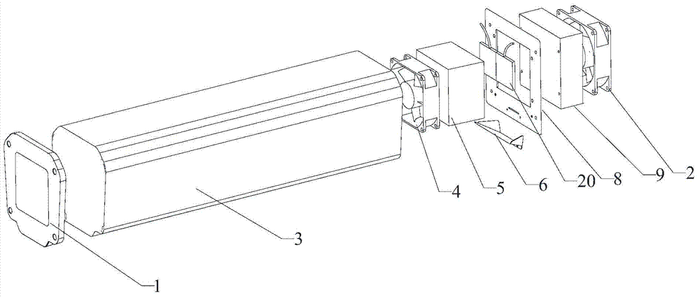
[0024] Please refer to figure 2 , a semiconductor cooling chip control device, including a temperature sensor 10, an MCU30, a DC motor drive chip 40 and a semiconductor cooling chip 20;

[0025] The control input terminals of the temperature sensor 10 and the DC motor driver chip 40 are respectively connected to the MCU 30, and the output terminals of the DC motor driver chip 40 are connected to the semiconductor cooling chip 20;

[0026] The MCU 30 is used to control the DC motor drive chip 40 to output DC...


PUM


Abstract

The invention discloses a semiconductor chilling plate control device. The semiconductor chilling plate control device comprises a temperature sensor, an MCU, a direct-current motor driver chip and a semiconductor chilling plate, wherein both the control input end of the temperature sensor and the control input end of the direct-current motor driver chip are connected with the MCU, the output end of the direct-current motor driver chip is connected with the semiconductor chilling plate, the MCU is used for controlling the direct-current motor driver chip to output direct currents to drive the semiconductor chilling plate to work according to the temperature value detected by the temperature sensor, and the output current of the direct-current motor driver chip can be adjusted. The invention further discloses a surveillance camera. According to the semiconductor chilling plate control device and the surveillance camera, due to the fact that the semiconductor chilling plate is driven by the direct-current motor driver chip with the adjustable output current, the service life of the semiconductor chilling plate is prolonged greatly.

Description

technical field [0001] The invention relates to the refrigeration field, in particular to a semiconductor refrigeration chip control device and a monitoring camera. Background technique [0002] In some areas, the outdoor temperature is often higher than 45°C in summer and lower than -20°C in winter. The working temperature of security cameras is generally around -10°C-60°C. In these areas, it may not be used normally, or the service life Greatly reduced. In addition, in humid places, although some security cameras have an IP66 waterproof and dustproof rating, it is inevitable that water vapor in the product will interfere with the image quality, so it is necessary to integrate cooling / dehumidification inside the security camera, or provide it outside the camera. Provide a low temperature and low humidity environment to ensure that these products can be used normally in high temperature, high humidity or low temperature areas. [0003] At present, refrigeration schemes are...

Claims


Application Information

Patent Timeline
Patent Type & Authority Applications(China)
IPC IPC(8): G05D23/20
Inventor 吴雪梅
Owner SHENZHEN INFINOVA
Learn More