
Treatment method of silica sol

A treatment method and technology of silica sol, applied in polishing compositions containing abrasives, etc., can solve the problems of increased chemical reaction speed, limited resources, scratches on wafer circuits, etc. The effect of improving uniformity

Inactive Publication Date: 2015-01-07
SHENZHEN LEAGUER MATERIAL +2
View PDF11 Cites 4 Cited by
  • Summary
  • Abstract
  • Description
  • Claims
  • Application Information

AI Technical Summary

Problems solved by technology

Alumina has a large particle size and high Mohs hardness, which often scratches the surface of the processed device and is difficult to clean after polishing
The hardness of ceria is moderate, but its resources are limited, so it is difficult to achieve industrial polishing
Locally too high temperature, high chemical reaction rate, severe chemical corrosion, resulting in poor surface uniformity
In addition, due to the increase in the chemical reaction rate caused by the local temperature out o

Method used


Image

  • Treatment method of silica sol

Examples


Embodiment 1

[0033] The content of silicon dioxide in ordinary silica sol is 20%, and the particle size is 20nm. The processing steps are as follows:

[0034] (1) Regenerate the strong acid type cation exchange resin and the strong base type anion exchange resin respectively;

[0035] (2) Mix the regenerated strong acid type cation exchange resin and the strong base type anion exchange resin in a volume ratio of 10:1 to obtain a strong acid and strong base mixed resin, and put it into a container with cooling, heating and stirring;

[0036] (3) Add ordinary silica sol into the container with strong acid and strong alkali mixed resin, control the temperature of silica sol to 30°C, and the weight ratio of strong acid and strong alkali mixed resin to silica sol is 1:30;

[0037] (4) Open the stirring device in the container, stir, make ordinary silica sol and strong acid and strong alkali mixed resin mix evenly;

[0038](5) In the process of step (4), add oxazole, the addition is 5% of the ...

Embodiment 2-7 and comparative example 1-2

[0041] Embodiments 2-7 and Comparative Examples 1-2 were carried out with reference to the steps of Embodiment 1, and the corresponding processing conditions were changed, as specifically listed in the table below.

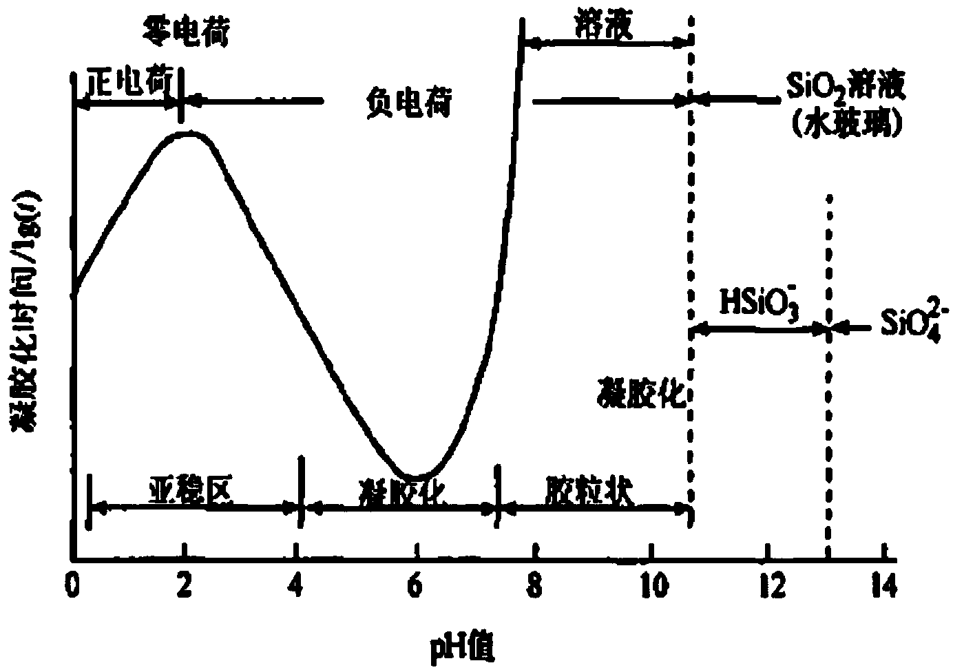
[0042] The common silica sol defined in the present invention refers to the silica sol having the following stability in different pH ranges. When the pH is 0-4, it is a metastable region. Silica sol can be stored in this state for a period of time. When the pH is 4-7, it is a gelation region. In this state, silica sol will gel and cannot be stored stably. When the temperature is 7-10.5, the silica sol still maintains the shape of colloidal particles and can be stored stably. Especially when the pH value is about 2 or 9, the gelation time is the longest, that is to say, the silica sol has a stable area in the acidic and alkaline areas, and can be stored stably in these two areas. The above are well-known and commonly used definition methods by those skilled in th...


PUM


Abstract

The invention relates to a treatment method of a silica sol and belongs to the technical fields of microelectronics auxiliary materials and ultra precision machining processes. The treatment method comprises the following steps: performing regeneration treatment on a strong acid cation exchange resin and a strong base cation exchange resin, respectively, and mixing to obtain a strong acid and strong base mixed resin; putting a common silica sol and the strong acid and strong base mixed resin together, and then stirring at a controlled temperature until even mixing; an imidazole compound, an organic acid and an organic base are added in the stirring process. The treatment method of the silica sol has the advantages that the defects of the common silica sol in the prior art in CMP polishing application are overcome, the application range of the common silica sol in CMP polishing is expanded, the common silica sol is treated so as to stably exist in the range of pH 1 to 12, and the particle stability can be maintained in the CMP polishing process and the temperature stability in the polishing process can be kept, and as a result, an even surface can be obtained.

Description

technical field [0001] The invention belongs to the technical field of microelectronic auxiliary materials and ultra-precision processing technology, and in particular relates to a treatment method for common silica sol. Background technique [0002] Chemical mechanical planarization (CMP) technology was introduced into the semiconductor silicon wafer process in the early 1990s, starting from interlayer insulating films such as oxide films, and extended to polymerized silicon electrodes and tungsten plugs (W-Plug) for conduction , STI (component separation), and the copper wiring process technology introduced at the same time as the high-performance drawing of the device has now become one of the key technologies. Chemical mechanical polishing has been proven to be the best and only technology capable of achieving global planarization. Chemical mechanical polishing is a process of chemical reaction, mechanical friction, and fluid dynamic pressure. Through the organic combin...

Claims


Application Information

Patent Timeline
IPC IPC(8): C09G1/02
CPCC09G1/02
Inventor 顾忠华潘国顺龚桦邹春莉罗桂海王鑫陈高攀
Owner SHENZHEN LEAGUER MATERIAL
Learn More