
Special beekeeping container

A container and large box technology, applied in the field of containers, can solve the problems of bee disturbance, high labor intensity, time-consuming and laborious, etc., and achieve the effect of small disturbance, saving time and manpower

Active Publication Date: 2015-01-07
马鞍山市求是仪表厂
View PDF6 Cites 8 Cited by
  • Summary
  • Abstract
  • Description
  • Claims
  • Application Information

AI Technical Summary

Problems solved by technology

This mode of operation has the following technical problems: ① labor intensity is high, time-consuming and labor-intensive, and inefficient, and the bees are disturbed during the moving process, which directly affects the production of honey; , it needs to stay for dozens of days, so it is necessary to set up tents in the bee farm, which is time-consuming and laborious; ③ Beekeepers often release bees on small roads, some small roads cannot be entered by large trailers, or large vehicles cannot turn around and return after entering; ④ Drive large vehicles A higher-level driver's license is required, and this type of driver's license needs to have sufficient driving experience to obtain it, and most beekeepers do not meet the requirements for obtaining a driver's license. If another driver is hired, the cost will increase

Method used


Image

  • Special beekeeping container
  • Special beekeeping container
  • Special beekeeping container

Examples


Embodiment Construction

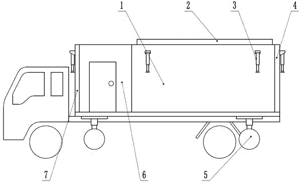
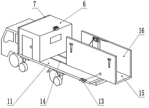
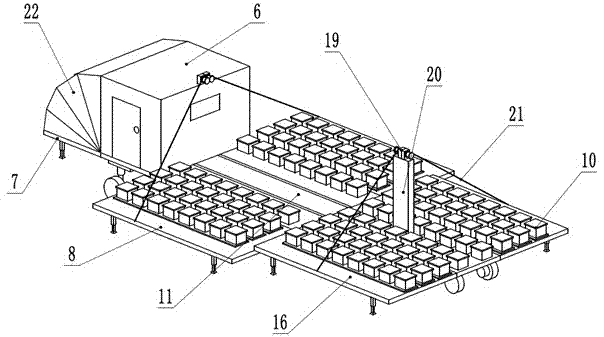
[0023] The present invention will be further described below in conjunction with the accompanying drawings and specific embodiments. For the convenience of description, the direction of the cab is set as the front, and the direction away from the cab is set as the rear. figure 2 In order to better display the internal structure, the side wall 8 of the large box and the rear wall 4 of the large box, the horizontal support plate 9, the pressure plate 18, the support rod 17, the tugboat 5 and other structures are removed.

[0024] like figure 1 , 2 , 3, and 4, the present invention includes a large casing 1 and a small casing 2. The small box 2 is located in the big box 1.

[0025] Described large box body 1 comprises large box body bottom plate 11, large box body side wall 8 and large box body rear wall 4, and described large box body bottom plate 11 is positioned at the bottom of large box body 1, and described large box body The bottom edge of the side wall 8 is hinged wi...


PUM


Abstract

The invention discloses a special beekeeping container, and belongs to the field of beekeeping. The special beekeeping container is characterized by comprising a large container and a small container; the small container is positioned in the large container; the large container comprises a large container bottom plate, large container side walls and a large container rear wall; one horizontal support plate or a plurality of horizontal support plates is arranged on the inner sides of the large container side walls, a pressure plate is further arranged above the uppermost horizontal support plate, one edge of each horizontal support plate and one edge of the pressure plate are hinged to the inner side of the corresponding large container side wall, a top corner at the other edge of each horizontal support plate and a top corner at the other edge of the pressure plate are respectively hinged to support rods, and the lower ends of the support rods are hinged to the large container bottom plate; the small container comprises a small container bottom plate and two small container side walls, and the two small container side walls are hinged to the small container bottom plate; drag wheels are connected to the rear of the lower side of the small container bottom plate; a pressure plate and horizontal support plates are hinged to the inner sides of the small container side walls, and a top corner at the other end of each horizontal support plate of the small container and a top corner at the other end of the pressure plate of the small container are respectively hinged to the corresponding support rods. Compared with the prior art, the special beekeeping container has the advantages of high automation degree and capability of saving time and labor.

Description

technical field [0001] The invention relates to a beekeeping device, in particular to a container suitable for collective transportation and a beekeeping platform. Background technique [0002] Beekeeping, or beekeeping, is the business of raising bees artificially and obtaining their products, including honey, royal jelly, propolis, pollen, beeswax and other products. The history of beekeeping has thousands of years, and the utilization of honey started from the era of fishing and hunting. [0003] Beekeepers need to change beekeeping locations frequently in order to catch up with the flowering period. The bee transfer method under the prior art is: whenever a new beekeeping site is reached, the beehives need to be removed from the car one by one, and the beehives need to be moved onto the car one by one when leaving. This mode of operation has the following technical problems: ① labor intensity is high, time-consuming and labor-intensive, and inefficient, and the bees ar...

Claims


Application Information

Patent Timeline
IPC IPC(8): B65D88/12A01K47/00E04B1/344E04H14/00
CPCA01K47/00B65D88/12E04B1/344E04H14/00
Inventor 刘加善
Owner 马鞍山市求是仪表厂
Learn More