
Equipment for automatic binding of wire harnesses with plastic cable ties

A plastic cable tie, automatic technology, applied to the parts of the binding machine, binding materials, paper/cardboard containers, etc., can solve the problems of the overall appearance error of the wire harness, the loose binding of the wire tie, the bulky volume, etc. The effect of high forming speed and high recognition

Active Publication Date: 2016-02-03
GUILIN UNIV OF ELECTRONIC TECH
View PDF6 Cites 0 Cited by
  • Summary
  • Abstract
  • Description
  • Claims
  • Application Information

AI Technical Summary

Problems solved by technology

[0004] However, the existing automatic binding machines (binding equipment) for plastic cable ties are bulky and expensive, and the phenomenon of loosening or loose binding of the cable ties often occurs.
The existing binding machine needs to be manually loaded. This manual loading method will cause the operator to work for a long time and cause finger fatigue and soreness, and the efficiency is very low and the working hours are long.
Due to manual operation, the remaining length of the tail end face of the cut plastic cable tie and the buckle head can not be guaranteed, resulting in errors in the overall appearance of the bundled wire harness

Method used


Image

  • Equipment for automatic binding of wire harnesses with plastic cable ties
  • Equipment for automatic binding of wire harnesses with plastic cable ties
  • Equipment for automatic binding of wire harnesses with plastic cable ties

Examples


Embodiment Construction

[0027] The mechanism of the present invention will be described in further detail below in conjunction with the accompanying drawings.

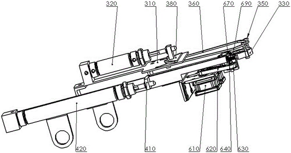
[0028] See figure 1 , figure 2 . An automatic binding device for plastic cable ties, comprising a base 100, a motor fixing mechanism (including 210, 220), a closing control mechanism (including 310, 320, 330, 340, 350, 360, 370, 380), a pushing mechanism (including 410 , 420), boosting mechanism (including 510, 540, 540, 550), tensioning mechanism and shearing mechanism (including 610, 620, 630, 640, 670, 690); the closing control mechanism, pushing mechanism, auxiliary The push mechanism, the tension mechanism, the shear mechanism, and the motor fixing mechanism are all arranged on the base; Figure 10 ) reaches the clamping groove, the clamping groove clamps the tail 830 of the plastic cable tie so that it cannot move, the closing control mechanism organizes the tied objects and places them on the plastic cable tie, and the plastic cabl...


PUM


Abstract

The invention provides equipment utilizing plastic ties to automatically bind wire harnesses. The equipment comprises a base, a motor fixing mechanism, a pushing mechanism, a boosting mechanism, a closure control mechanism, a tension mechanism and a shear mechanism, wherein the motor fixing mechanism is used for fixing a motor; the pushing mechanism is arranged on one side of the base and used for pushing a plastic tie tail part to a clamping groove; the boosting mechanism is arranged in the front of the base, connected with a boosting motor and used for pushing a plastic tie head part to pass through the plastic tie tail part; the closure control mechanism is arranged in the front of the base and used for arranging bound wire harnesses in order and placing the ordered wire harnesses on a plastic tie; and the tension mechanism and the shear mechanism are arranged in the front of the base and used for tensioning the plastic tie head part to realize binding and cutting off the redundant head part. The equipment is small in size, high in efficiency and low in cost, can automatically bind the wire harnesses and cut off the residual plastic tie, relieves the labor intensity, ensures a relatively stable tensioning force and achieves firm binding.

Description

technical field [0001] The invention relates to wire harness binding, in particular to a device capable of automatically tightening and binding wire harnesses and cutting plastic tie, which is used to realize automatic boost feeding, automatic alignment, automatic tensioning and binding (adjustable and relatively constant pulling force), Automatic cutting, automatic discharge of cutting materials and other processes. technical background [0002] With the continuous development of science and technology, electronic products are developing in the direction of large capacity and high density. The ports of plug-in boards are becoming more and more dense, and the wiring harnesses are becoming more and more dense. If these wiring harnesses are allowed to be placed randomly, the layout will be messy, and it will make product maintenance more difficult, and it will also affect the performance of the whole machine. This problem can be solved by neatly bundling the wiring harness. ...

Claims


Application Information

Patent Timeline
Patent Type & Authority Patents(China)
IPC IPC(8): B65B13/04B65B13/22B65B27/06
CPCB65B13/04B65B13/22B65B27/06
Inventor 李春泉尚玉玲赵帅峰张明孔令旺李彩林李元鑫郭丽娜刘丹莫慧光
Owner GUILIN UNIV OF ELECTRONIC TECH
Learn More