
Powerless Swivel Clamp

A technology of power rotation and clamp, applied in the field of clamp components, can solve problems such as pressure change, leakage, instability, etc., and achieve the effects of stable temperature change control, energy saving and high stability

Active Publication Date: 2016-01-27
大连光洋自动化系统有限公司
View PDF6 Cites 0 Cited by
  • Summary
  • Abstract
  • Description
  • Claims
  • Application Information

AI Technical Summary

Problems solved by technology

[0004] The technical problem to be solved by the present invention is to provide a non-powered rotary clamp to solve the problems of pressure change, leakage and instability during the clamping process; the high-pressure sealed nitrogen spring clamp works without a power source, high temperature and high pressure Issues of sealing, stability control, lubrication, energy saving and cost reduction under

Method used


Image

  • Powerless Swivel Clamp
  • Powerless Swivel Clamp
  • Powerless Swivel Clamp

Examples


Embodiment Construction

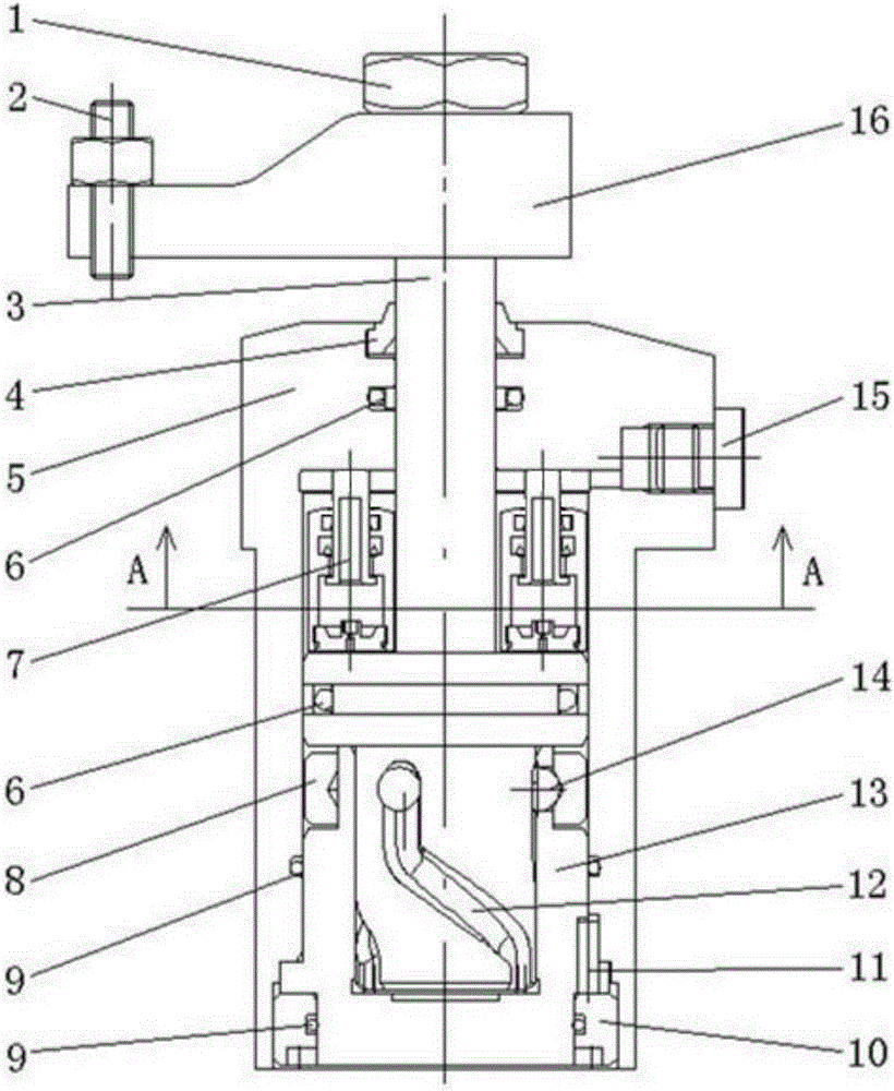
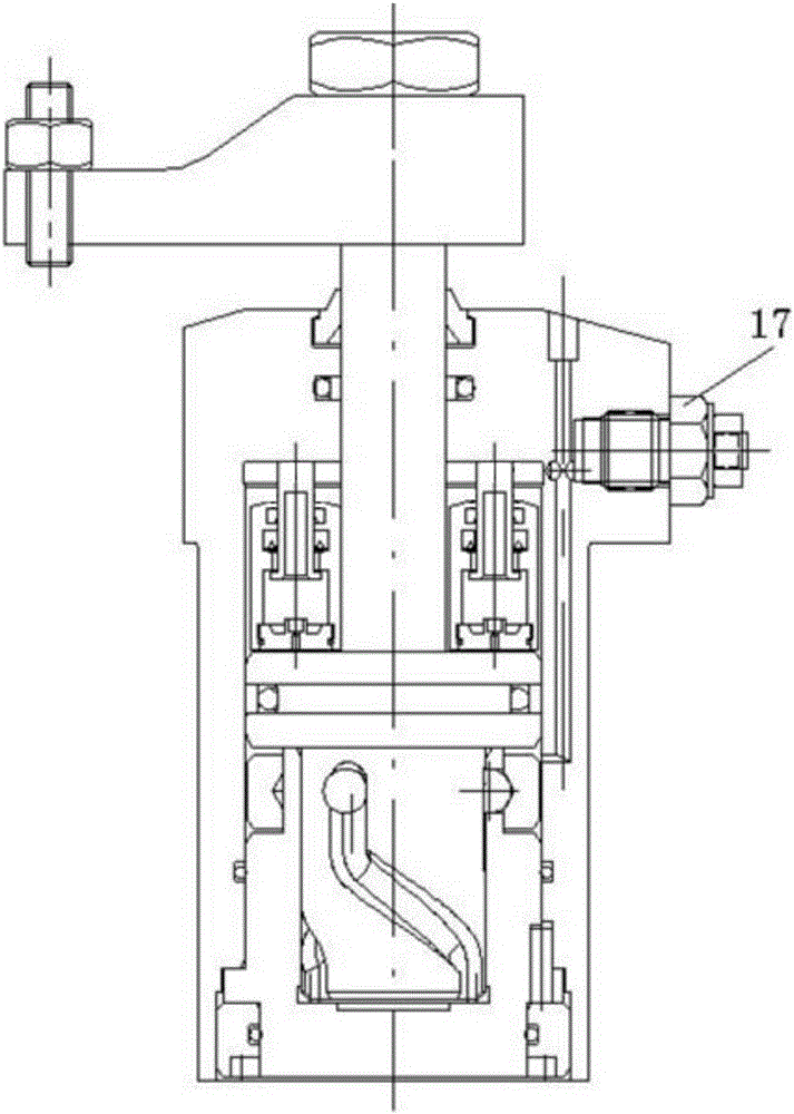
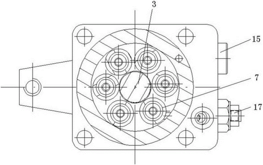
[0020] Such as Figure 1-Figure 4 As shown, the unpowered rotary clamp includes a rotary cylinder piston 3, a cylinder body 5, a nitrogen spring 7, a cylinder end cover 10, and a compression arm 16, and the inner cavity at the bottom of the cylinder body 5 is fixed and installed through a fixing ring positioning pin 11. There is a fixed ring 13 and the inner cavity of the oil cylinder body 5 and the fixed ring 13 are sealed by an O-ring 9, and an oil cylinder end cover 10 is installed between the oil cylinder body 5 and the fixed ring 13, and the oil cylinder end cover 10 and the fixed ring 13 Between them are sealed by O-rings 9; the inner chamber of the oil cylinder body 5 is equipped with a rotating oil cylinder piston 3, and the rotating oil cylinder piston 3 includes a piston rod A, a large end and a rotating part connected in sequence to form an integral structure; the rotating part is provided with There are several rotating guide grooves 12, the rotating part extends i...


PUM


Abstract

The invention discloses an unpowered rotary holding device. The unpowered rotary holding device comprises a rotary oil cylinder piston, an oil cylinder body, a plurality of nitrogen springs, an oil cylinder end cover and a pressure arm, wherein the rotary oil cylinder piston is movably mounted in the inner chamber of the oil cylinder body; and the nitrogen springs are placed on the upper surface of the big-end part of the rotary oil cylinder piston and around a piston rod A. According to the invention, as the structure that the upper inner chamber of the oil cylinder body is filled with oil to seal the nitrogen springs is adopted, the sealing problem of the nitrogen springs at high temperature and high pressure is effectively solved; the structural design is simple and reasonable; the manufacturing cost is low; the nitrogen springs and the temperature variation can be controlled stably; meanwhile, owing to the oil lubrication function, good lubricity between the nitrogen springs and the oil cylinder body, as well as between the rotary oil cylinder piston and the oil cylinder body, is ensured; through propulsion of the high-pressure sealed nitrogen springs and rotation of the rotary oil cylinder piston, workpieces are clamped without an additional external power source; and the nitrogen springs are adopted for pressure maintaining and clamping, so that leakage is avoided, the stability is high, energy saving and no pollution are realized, the clamping height can be adjusted and the clamping stroke is large.

Description

technical field [0001] The invention relates to the technical field of clamp elements, in particular to a non-powered rotary clamp. Background technique [0002] With the continuous advancement of science and technology, the requirements for clamps in the industrial field are getting higher and higher. It is required that the clamps not only meet the various needs of the mechanical structure, but also require the miniaturization and high performance of the clamp components. Conventional clamp elements used in the prior art, such as single-action clamps (hydraulic or pneumatic clamp, spring force release), double-action clamps (hydraulic or pneumatic clamp, spring force release) and hydraulic Loosening spring clamping, etc. At present, the clamps used in various industries in various countries in the world are mainly pneumatic and hydraulic. The clamping force of the pneumatic clamp is small, and the hydraulic clamp needs to continuously replenish power when it is working, w...

Claims


Application Information

Patent Timeline
Patent Type & Authority Patents(China)
IPC IPC(8): B25B11/00
CPCB23Q3/082
Inventor 姜雨于德海陈虎田朋于本宏许钢鲍文禄周吉贞
Owner 大连光洋自动化系统有限公司
Learn More