


Quick Research
Generate reliable direction feasibility study reports for your R&D in just a few steps.

Technical Q&A
Discover and master advanced knowledge NOW. Basics, ideas, possibilities, all at once.

Find Solutions
As an expert in R&D theories, this can generate solutions to your technical problems instantly.

Evaluate Feasibility
Analyze your overall solution with one click, know your potential R&D risks in advance.

Monitor Landscape
Get weekly tech updates, stay abreast of the latest tech innovations and key insights.
Punching machine capable of automatically controlling punching depth
A punching machine and depth technology, applied in the direction of boring/drilling, drilling/drilling equipment, manufacturing tools, etc., can solve problems such as low production efficiency, hidden safety hazards, and high labor intensity of workers, so as to reduce wear and tear , the effect of increasing the service life
- Summary
- Abstract
- Description
- Claims
- Application Information
AI Technical Summary
Problems solved by technology
Method used
Image

Examples
Embodiment 1
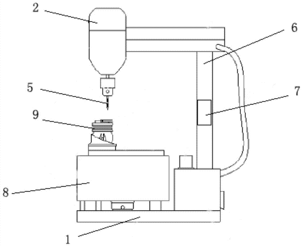
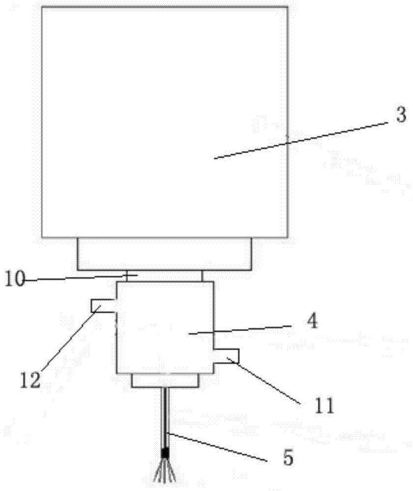
[0016] A drilling machine for automatically controlling the drilling depth, comprising a base 1, a motor 2 and a control device, the power output shaft 3 of the motor 2 is connected with an internal cooling joint 4, the internal cooling joint 4 is connected with a hollow drill bit 5, and the base 1 is provided with There is a support 6, on which a lifting cylinder 7 is arranged, the lifting cylinder 7 is connected to the control device, the motor 2 is fixedly connected to the support 6, a workbench 8 is also arranged on the base 1, and a clamping mechanism 9 is arranged on the workbench 8 .
[0017] The internal cooling joint 4 is composed of a main shaft 10, a water inlet 11 and a water outlet 12. The upper end of one side of the main shaft 10 is provided with a water outlet 12, and the lower end of the other side of the main shaft 10 is provided with a water inlet 11. The water inlet 11 and the water outlet 12 are connected with the main shaft 10 are connected by sealed bear...
Embodiment 2
[0021] A drilling machine for automatically controlling the drilling depth, comprising a base 1, a motor 2 and a control device, the power output shaft 3 of the motor 2 is connected with an internal cooling joint 4, the internal cooling joint 4 is connected with a hollow drill bit 5, and the base 1 is provided with There is a support 6, on which a lift cylinder 7 is arranged, the lift cylinder 7 is connected to the control device, the motor 2 is fixedly connected to the support 6, a workbench 8 is also arranged on the base 1, and a clamping mechanism 9 is arranged on the workbench 8 .
[0022] The control device includes a PLC controller and a drilling depth input device, the output end of the drilling depth input device is connected to the input end of the PLC controller, and the output end of the PLC controller is connected to the lifting cylinder 7 .
[0023] The clamping mechanism includes a bottom plate and a clamping part, the clamping part is arranged on the bottom plat...
PUM
 Abstract
Description
Claims
Application Information
 - R&D Engineer
- R&D Manager
- IP Professional
- Industry Leading Data Capabilities
- Powerful AI technology
- Patent DNA Extraction
Browse by: Latest US Patents, China's latest patents, Technical Efficacy Thesaurus, Application Domain, Technology Topic, Popular Technical Reports.
© 2024 PatSnap. All rights reserved.Legal|Privacy policy|Modern Slavery Act Transparency Statement|Sitemap|About US| Contact US: help@patsnap.com