Cleaning machine of oil tank trucks

A washing machine and oil tanker technology, which is applied in the direction of cleaning hollow objects, cleaning methods and appliances, chemical instruments and methods, etc., can solve the problem of increasing the complexity of the operation of the oil tanker washing machine, increasing the driving source of the oil tanker washing machine, etc. question

Active Publication Date: 2015-01-07
乐清市金宇石化设备有限公司
View PDF7 Cites 8 Cited by
  • Summary
  • Abstract
  • Description
  • Claims
  • Application Information

AI Technical Summary

Problems solved by technology

[0003] In order to solve the above problems, the Chinese patent application number CN201220275027.8 discloses an oil tank car cleaning machine, which includes a base on which a nozzle device, a horizontal adjustment and distance adjustment mechanism of the nozzle device and a lifting mechanism of the nozzle device are arranged. , the base is fixed on the cleaning site, the distance adjustment mechanism includes the first swing rod, the second swing rod and the swing driving mechanism that drives the first swing rod and the second swing rod to swing relatively horizontally, and the nozzle device includes a base that matches the inlet of the oil tank The end of the nozzle fixed bracket away from the base is provided with a nozzle extension rod and a rotary drive mechanism for the nozzle extension rod. The direction adjustment mechanism includes a rotary cylinder installed on the base to drive the nozzle fixed bracket to rotate. After the nozzle device enters the oil tank, the direction of the nozzle device is adjusted by rotating the cylinder, which invisibly increases the driving source that needs to be controlled for the tank truck cleaning machine, and increases the complexity of the operation of the tank truck cleaning machine

Method used


Image

  • Cleaning machine of oil tank trucks
  • Cleaning machine of oil tank trucks
  • Cleaning machine of oil tank trucks

Examples


Embodiment Construction

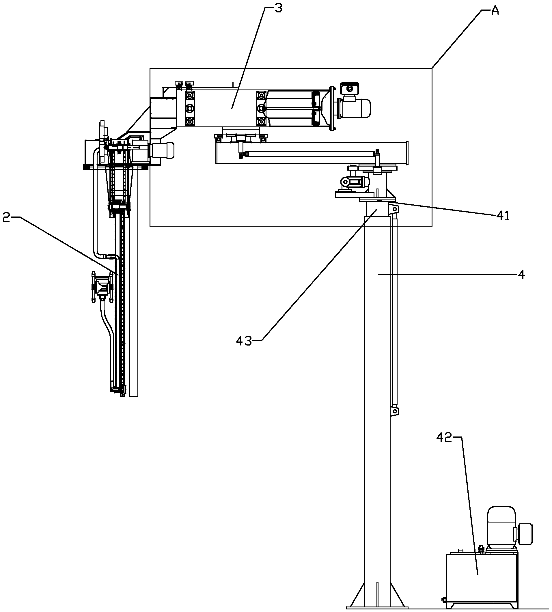
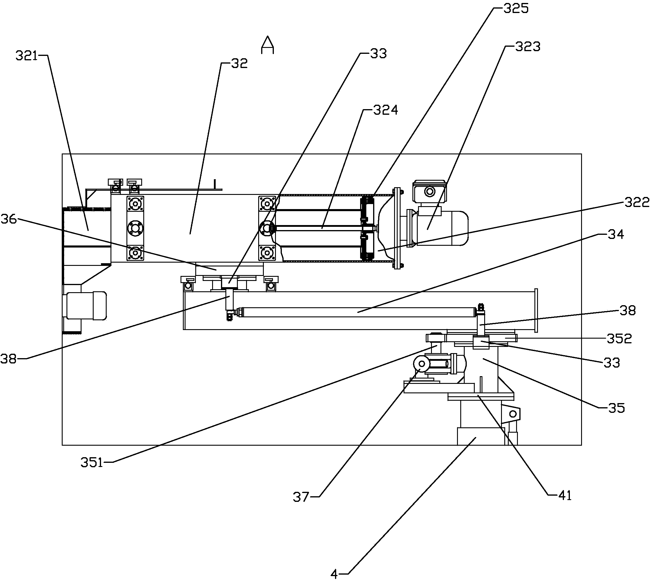
[0030] Such as figure 1 — Figure 6As shown, the present invention discloses an oil tank truck cleaning machine, which includes a base 1, on which a nozzle device 2, a horizontal direction adjustment and distance adjustment mechanism 3 of the nozzle device 2 and a lifting mechanism 4 of the nozzle device 2 are arranged, and the horizontal The steering and distance adjustment mechanism 3 includes a first fork 31 that is horizontally swayed at one end on the lifting platform 41 of the elevating mechanism 4, and a second fork 32 that is horizontally oscillating at the other end of the first fork relative to the lifting platform 41 and A swing driving mechanism that drives the first swing rod 31 and the second swing rod 32 to swing horizontally. The spray head device 2 is fixedly installed on the end of the second swing rod 32 away from the first swing rod 31. The first swing rod 31 is horizontally and parallelly arranged with The main linkage rod 34, the two ends of the main li...


PUM


Abstract

The invention relates to a cleaning machine of oil tank trucks. The cleaning machine comprises a base, wherein a spray head device, a horizontal direction and distance adjustment mechanism of the spray head device and a lifting mechanism of the spray head device are arranged on the base. The horizontal direction and distance adjustment mechanism comprises a first oscillating bar, a second oscillating bar and an oscillating driving mechanism, wherein one end of the first oscillating bar is arranged on a lifting platform of the lifting mechanism in a horizontal oscillating mode, the second oscillating bar is arranged at the other end of the lifting platform relative to the first oscillating bar in a horizontal oscillating mode, and the oscillating driving mechanism drives the first oscillating bar and the second oscillating bar to oscillate horizontally. The spray head device is fixedly arranged at the end of the second oscillating bar far away from the first oscillating bar, a main linkage rod is horizontally arranged on the first oscillating bar in a parallel way, and auxiliary linkage rods fixedly connected with the second oscillating bar and the lifting platform respectively are hinged at two ends of the main linkage rod. By adopting the scheme, the spray head device of the cleaning machine of the oil tank trucks is simplified, and the direction of the cleaning machine can be adjusted.

Description

technical field [0001] The invention relates to a cleaning device for the inner wall of an oil tank car, in particular to a cleaning machine for an oil tank car. Background technique [0002] At present, steam fumigation is the main method for cleaning the inner wall of train tank cars in my country. It is to pass steam into the tank car to be cleaned, and use the heat energy of the steam to heat the inner wall of the tank car, so that the residual materials attached to the inner wall of the tank car are volatilized and discharged into the atmosphere. After the fumigation is completed, the cleaning worker goes down to the tank car, uses a special brush dipped in cleaning agent to scrub the inner wall, rinses it with clean water, and then sweeps away the residue and passes it into hot air for drying to achieve the purpose of cleaning the inner wall of the tank car. The tanker is fumigated and cleaned with the open mouth. During the cleaning process, the flammable and toxic wa...

Claims


Application Information

Patent Timeline
IPC IPC(8): B08B9/093
CPCB08B9/0936
Inventor 张国柱王信金哲
Owner 乐清市金宇石化设备有限公司
Why Eureka
Try Eureka