Method for determining effective thermal conductance of micro-bolometer

A technology of microbolometer and effective heat, which is applied in the field of infrared detectors, can solve the problems of error, affecting the effective thermal conductivity value, and affecting the accuracy of thermal parameters of the microbolometer, so as to achieve accurate and precise thermal conductivity value high effect

Inactive Publication Date: 2014-12-31
UNIV OF ELECTRONIC SCI & TECH OF CHINA
View PDF0 Cites 2 Cited by
  • Summary
  • Abstract
  • Description
  • Claims
  • Application Information

AI Technical Summary

Problems solved by technology

[0016] The disadvantages of this method are: (1) This method requires the device to work in a DC state, that is, f=0HZ, to be more accurate. When the current is in a pulse state, this method will have a huge error; (2) This method There is an approximation for the flat band part of the curve, which will affect the effective thermal conductivity value to a certain extent
[0017] Therefore, the existing methods for determining the effective thermal conductivity of the micro-bridge structure of the microbolometer all affect the accuracy of the thermal parameters of the microbolometer to a large extent, and a more accurate method for determining the effective thermal conductivity is needed

Method used


Image

  • Method for determining effective thermal conductance of micro-bolometer
  • Method for determining effective thermal conductance of micro-bolometer
  • Method for determining effective thermal conductance of micro-bolometer

Examples


Embodiment Construction

[0040] The specific steps of the method for determining the effective thermal conductance of a microbolometer according to an embodiment of the present invention will be described in detail below with reference to the accompanying drawings.

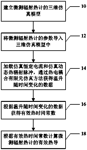
[0041] figure 1 is a schematic flowchart of a method for determining the effective thermal conductance of a microbolometer according to an embodiment of the present invention.

[0042] like figure 1 As shown, in an embodiment of the present invention, in step 10, a three-dimensional simulation model of the microbolometer may be established first.

[0043] In the embodiments of the present invention, any suitable method may be used to establish a three-dimensional simulation model of the microbolometer. For example, in one embodiment, a three-dimensional simulation model of a microbolometer can be built using MEMS (micro-electromechanical system) software.

[0044] In the embodiment of the present invention, the three-dimensional simula...


PUM


Abstract

An embodiment of the invention discloses a method for determining the effective thermal conductance of a micro-bolometer. The method includes: building a three-dimensional simulation model of the micro-bolometer; importing the parameters of the micro-bolometer into the three-dimensional simulation model; loading simulation constant current on the three-dimensional simulation model, loading a simulation dynamic thermal radiation pulse after simulation temperature is stabilized, and using a thermoelectric coupling finite element simulation method to obtain data of temperature rise change along with time; acquiring an effective thermal time constant according to the data; calculating the effective thermal conductance of the micro-bolometer according to the effective thermal time constant. The method has the advantages that the method is based on the precise three-dimensional simulation model, the actual size and processing line parameters of the micro-bolometer are used, device working states are simulated in real through finite element dynamic thermoelectric coupling analysis so as to calculate the effective thermal conductance of the micro-bolometer, and the calculated effective thermal conductance is more accurate than the effective thermal conductance theoretically calculated.

Description

[0001] technical field [0002] The invention relates to the technical field of infrared detectors, in particular to a method for determining the effective thermal conductivity of a microbolometer. [0003] Background technique [0004] The working principle of the microbolometer is that the light-absorbing layer receives external infrared radiation to cause the temperature of the device to change, and the temperature change causes the resistance of the sensitive film to change. The change in electrical properties is detected by the electrode and transmitted to the readout circuit to complete the signal. processing and imaging. There are many parameters that affect the performance of microbolometers, including heat capacity, thermal conductivity, thermal time constant, infrared effective radiation area received, temperature coefficient of resistance of heat-sensitive film, noise, etc. [0005] From the working principle of the microbolometer, it can be known that under the...

Claims


Application Information

Patent Timeline
IPC IPC(8): G06F19/00G06F17/50G01J5/20
Inventor 陈超张龙王涛胡晓赵源蒋亚东马家峰
Owner UNIV OF ELECTRONIC SCI & TECH OF CHINA
Why Eureka
Try Eureka