Radio clock

A radio and clock technology, applied in the field of radio clocks, can solve the problem of high power consumption of time information

Active Publication Date: 2014-12-31
SEIKO TIME CREATION INC
View PDF11 Cites 3 Cited by
  • Summary
  • Abstract
  • Description
  • Claims
  • Application Information

AI Technical Summary

Problems solved by technology

However, the power consumption of extracting time information etc. by the receiving module from the satellite signal received from the GPS satellite is large
So the question is, how long can a battery powered radio clock last

Method used


Image

  • Radio clock
  • Radio clock
  • Radio clock

Examples


Embodiment Construction

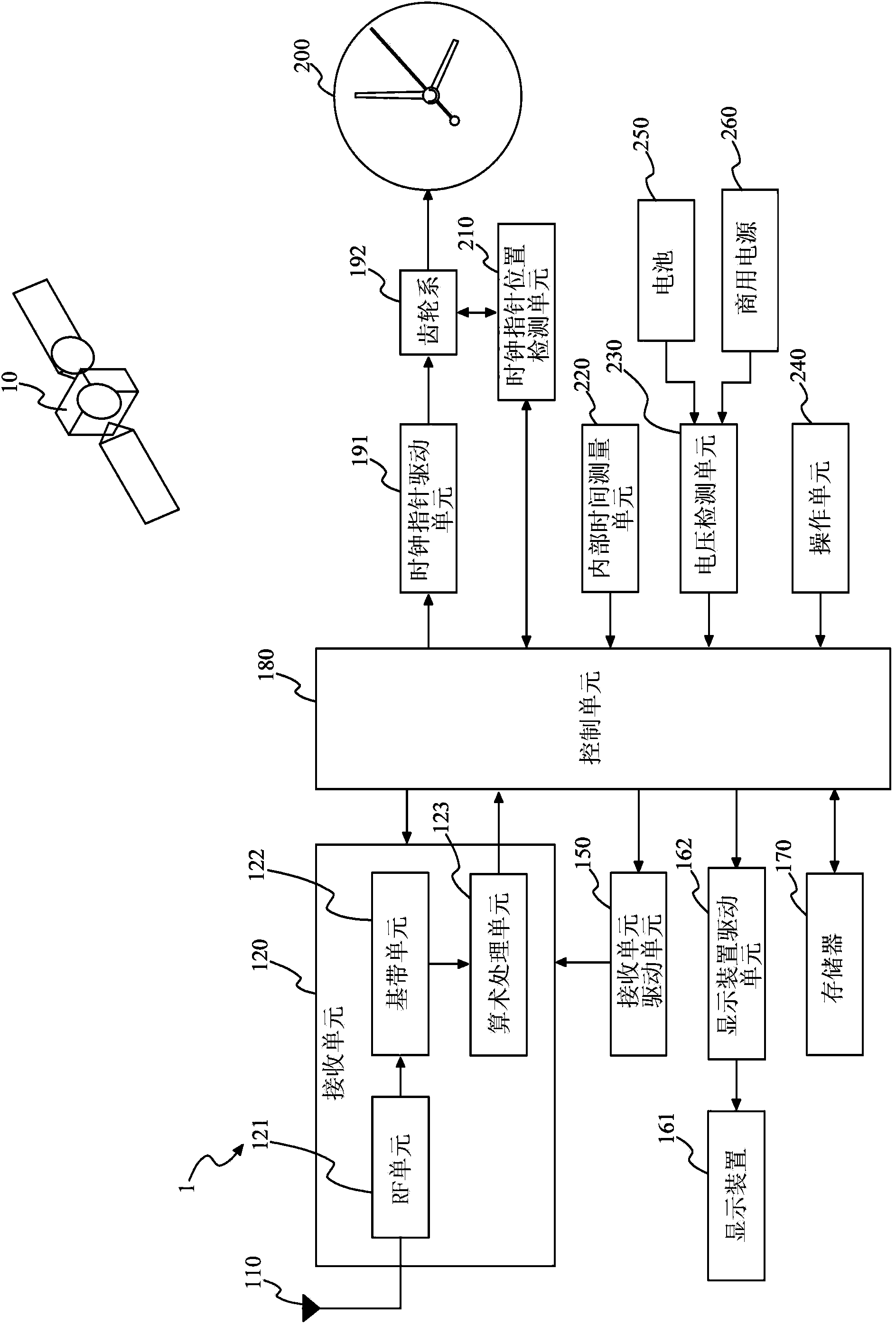
[0027] First, refer to figure 1 The structure of this embodiment will be described. The radio clock 1 of this embodiment includes: a GPS antenna 110, a receiving unit 120, a receiving unit driving unit 150, a display device 161, a display device driving unit 162, a memory 170, a control unit 180, a clock pointer driving unit 191, a gear train 192, A time display unit 200 , a clock hand position detection unit 210 , an internal time measurement unit 220 , a voltage detection unit 230 and an operation unit 240 .

[0028] The GPS antenna 110 is an antenna for receiving satellite signals transmitted from the GPS satellite 10 . The GPS antenna 110 outputs the received satellite signals to the receiving unit 120 . exist figure 1 In , only one GPS satellite 10 is shown for simplicity.

[0029] The receiving unit 120 includes: an RF (Radio Frequency, radio frequency) unit 121 , a baseband unit 122 and an arithmetic processing unit 123 . The receiving unit 120 performs receiving p...


PUM


Abstract

A radio clock including: an antenna configured to receive a satellite signal transmitted from GPS satellite; a receiving unit configured to perform a receiving process to acquire information contained in the satellite signal received by the antenna within a predetermine upper limit period; and a control unit configured to change the number of receiving processes to be performed in a predetermined period and change the upper limit period in accordance with a total sum of durations of the receiving processes performed in the predetermined period.

Description

technical field [0001] This invention relates to radio clocks. Background technique [0002] The radio clock receives satellite signals transmitted from GPS (Global Positioning System, Global Positioning System) satellites, and corrects the time of the internal clock based on time information contained in the received satellite signals. By doing this, radio clocks display highly accurate time. However, power consumption for extracting time information and the like from satellite signals received from GPS satellites by the receiving module is large. So the question is, how long can a battery-operated radio clock last. Patent Documents 1 to 3 disclose radio clocks that consume less power and have a longer operating time. [0003] [Prior art literature] [0004] [Patent Document] [0005] [Patent Document 1] Japanese Unexamined Patent Application Publication No. 2011-226813 [0006] [Patent Document 2] Japanese Unexamined Patent Application Publication No. 2011-226933 ...

Claims


Application Information

Patent Timeline
Patent Type & Authority Applications(China)
IPC IPC(8): G04R20/04
CPCG04R20/04G04R20/02
Inventor 今村美由纪多湖元浩金泉贵之
Owner SEIKO TIME CREATION INC
Why Eureka
Try Eureka