
Hydraulic-hydraumatic comprehensive driving axle gear box body

A technology for axle gearboxes and boxes, which is applied in the directions of transmission boxes, transmission parts, gear lubrication/cooling, etc., which can solve the problems that drive axle gearboxes cannot be shared, affect the efficiency of line operation, and complicate power transmission systems. Compact, takes up little space, and improves sealing reliability

Active Publication Date: 2015-06-10
CHANGZHOU RUITAI ENG MASCH CO LTD +1
View PDF5 Cites 0 Cited by
  • Summary
  • Abstract
  • Description
  • Claims
  • Application Information

AI Technical Summary

Problems solved by technology

[0004] The existing large-scale railway maintenance vehicle axle gearbox products mainly have the following shortcomings and deficiencies during use: ①It can only adapt to a single transmission mode. Therefore, in order to adapt to different operating conditions, different power transmission modes use two The running transmission system, especially the drive axle gearbox, cannot be shared. In the railway maintenance vehicle, axle gearboxes with different functions need to be installed, which makes the power transmission system of the vehicle more complicated, reduces the reliability of the system, increases the weight of the vehicle, costs and Waste a lot of body space
②Axle gearbox occupies a large space on the bogie, so there is no space to install the axle-disk foundation brake device required for high-speed vehicle braking, which limits the increase in vehicle speed
③The maximum driving speed is basically about 100km / h, and a few can reach 120km / h; in the case of more and more concentrated transportation capacity and faster and faster operation speed of the current line, it is bound to affect the operating efficiency of the line to a certain extent, especially Cannot meet the requirements of high-speed railway and passenger dedicated line

Method used


Image

  • Hydraulic-hydraumatic comprehensive driving axle gear box body
  • Hydraulic-hydraumatic comprehensive driving axle gear box body
  • Hydraulic-hydraumatic comprehensive driving axle gear box body

Examples


Embodiment Construction

[0025] The present invention is described in further detail below in conjunction with the embodiment that accompanying drawing provides.

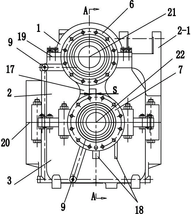
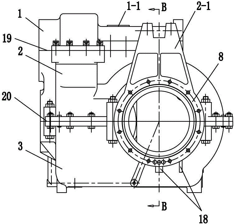
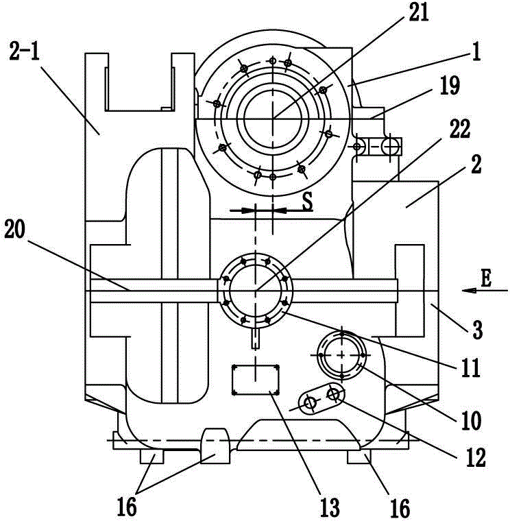
[0026] Such as figure 1 , 2 , 3, 4, 5, 6, 7, and 8, a hydraulic-hydraulic comprehensive transmission axle gearbox box body, including a box cover 1, an upper box body 2 and a lower box body 3, the box cover 1, The upper box body 2 and the lower box body 3 are fixedly connected by bolts to form a box body, and the box body is provided with a pull arm mounting seat 2-1, and the box body is provided with a motor mounting flange seat 4, and a motor input spline shaft bearing seat 5. The input gear shaft bearing seat 6, the intermediate shaft bearing seat 7 and the output shaft bearing seat 8; the box has an upper split surface 19 and a lower split surface 20, and the upper split surface 19 and the lower split surface 20 are respectively parallel to the horizontal plane; the motor mounting flange seat 4, the motor input spline shaft bearing se...


PUM


Abstract

The invention discloses a hydraulic-hydraumatic comprehensive driving axle gear box body for a high-speed railway maintaining vehicle. The hydraulic-hydraumatic comprehensive driving axle gear box body comprises a box cover, an upper box body and a lower box body, wherein a motor mounting flange base, a motor input spline shaft bearing base, an input gear shaft bearing base, a middle shaft bearing base and an output shaft bearing base are arranged on the box body; the box body is provided with an upper subdivision part and a lower subdivision part; the motor mounting flange base, the motor input spline shaft bearing base and the input gear shaft bearing base have the same first central axis; the first central axis is located on the upper subdivision part; a second central axis of the middle shaft bearing base and a third central axis of the output shaft bearing base are respectively located on the lower subdivision part and are vertical to each other; the first central axis and the second central axis of the middle shaft bearing base are parallel to each other; the first central axis is deviated from the second central axis for a distance S; the deviating direction is away from one side of a pull arm mounting base. The hydraulic-hydraumatic comprehensive driving axle gear box body has the advantages of compact structure, small volume, reasonable layout and easiness in manufacturing and maintaining.

Description

technical field [0001] The invention relates to a rail vehicle power transmission device, in particular to a driving axle gearbox of a high-speed railway maintenance vehicle. Background technique [0002] With the rapid development of high-speed railways in my country, the speed of existing railways has been increased to 160-200km / h on a large scale, and large-scale passenger lines of 200km / h and above have been completed and opened to traffic. The maintenance efficiency and quality also put forward stricter requirements. The original large-scale railway maintenance vehicles in China run at a slow speed, and the marshalling maintenance operation takes a long time to reflect, which affects the efficiency of maintenance operations, and can no longer meet the time efficiency requirements for emergency repairs of high-speed railway lines. For this reason, high-speed, high-efficiency and high-reliability large-scale railway maintenance vehicles will become a new demand for railwa...

Claims


Application Information

Patent Timeline
Patent Type & Authority Patents(China)
IPC IPC(8): F16H57/02F16H57/027F16H57/029F16H57/03F16H57/04
CPCF16H57/02F16H57/021F16H57/027F16H57/03F16H57/0405F16H57/0424
Inventor 胡高华陈亚东朱朝江杨俊杰丁忍程龙
Owner CHANGZHOU RUITAI ENG MASCH CO LTD
Learn More