Multi-rotation encoder
A technology of rotary encoder and rotating shaft, applied in the direction of converting sensor output, instruments, measuring devices, etc., can solve the problems of rising cost, difficulty in high durability, poor maintenance of backup batteries, etc., and achieve the effect of accurate detection
- Summary
- Abstract
- Description
- Claims
- Application Information
AI Technical Summary
Problems solved by technology
Method used
Image

Examples
Embodiment approach 1
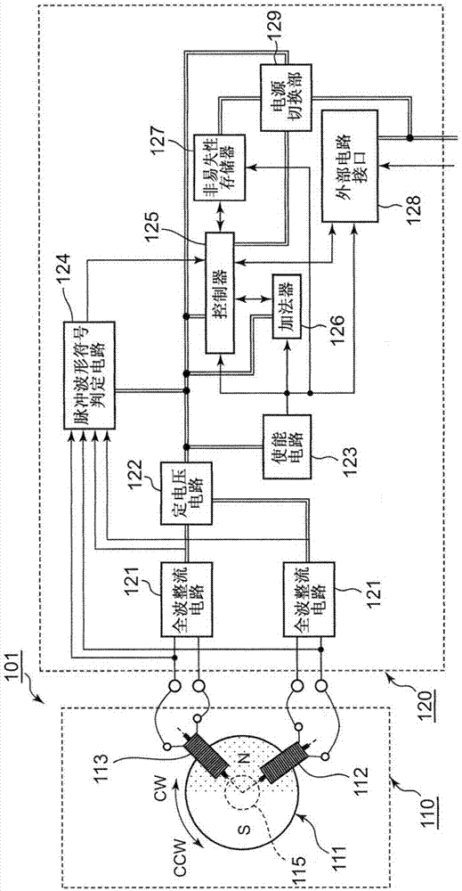
[0042] figure 1 The configuration of the batteryless multi-rotary encoder 101 according to Embodiment 1 of the present invention is shown in . The batteryless multi-rotary encoder 101 of this embodiment is a multi-rotary encoder that detects and stores the rotation direction and the number of revolutions of the rotary shaft without receiving power supply from the outside, and is roughly classified into: a rotation detection mechanism 110; The processing circuit 120 is electrically connected to the rotation detection mechanism 110 .
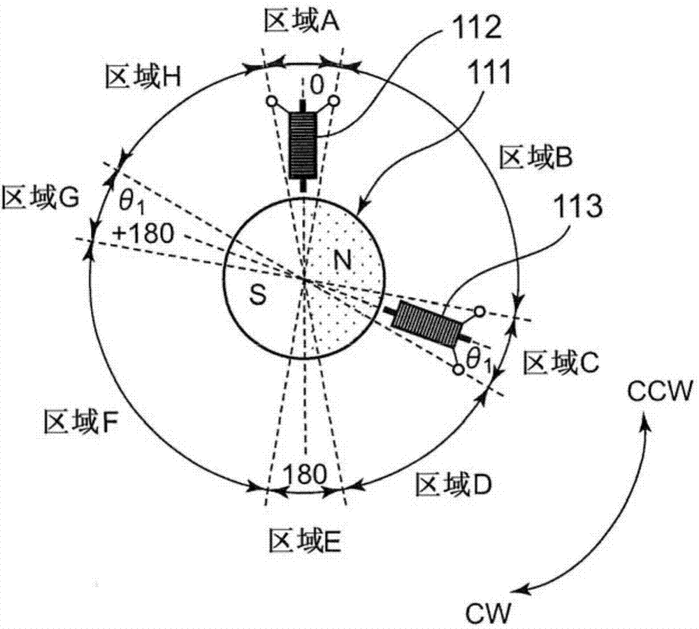
[0043] Such as figure 2 As shown, the rotation detection mechanism 110 has a magnet 111 and detection coils 112 and 113 , and is configured to detect the rotation of a rotation shaft 115 . In addition, the rotating shaft 115 corresponds to, for example, an output shaft (rotating shaft) of a motor, etc., but is not limited thereto, and may correspond to a rotating body rotatable about an axial direction.
[0044] The magnet 111 has a disc shap...
Embodiment approach 2
[0068] refer to Figure 8 The batteryless multi-rotary encoder 102 according to Embodiment 2 of the present invention will be described.
[0069] The batteryless multi-rotary encoder 102 of the present embodiment also includes a rotation detection mechanism 110 , and a signal processing circuit electrically connected to the rotation detection mechanism 110 , as in the aforementioned batteryless multi-rotation encoder 101 . The battery-less multi-rotation encoder 102 of this embodiment is different from the above-described battery-less multi-rotation encoder 101 in that it includes a signal processing circuit 131 instead of the signal processing circuit 120 . In addition, the difference between the signal processing circuit 120 and the signal processing circuit 131 is that the nonvolatile memory 127 is arranged outside the signal processing circuit. Other configurations of the signal processing circuit 131 are the same as those of the signal processing circuit 120 .
[0070] ...
Embodiment approach 3
[0072] refer to Figure 9 The batteryless multi-rotary encoder 103 according to Embodiment 3 of the present invention will be described.
[0073] The battery-less multi-rotary encoder 103 of this embodiment also has a rotation detection mechanism 110 and a signal processing circuit electrically connected to the rotation detection mechanism 110 similarly to the above-mentioned battery-less multi-rotation encoder 101 . The battery-less multi-rotary encoder 103 of the present embodiment is different from the battery-less multi-rotary encoder 101 described above in that it includes a signal processing circuit 132 instead of the signal processing circuit 120 . The difference between the signal processing circuit 120 and the signal processing circuit 132 is that the full-wave rectification circuit 121 and the constant voltage circuit 122 are arranged between the rotation detection mechanism 110 and the signal processing circuit 132 outside the signal processing circuit. Other confi...
PUM
 Abstract
Description
Claims
Application Information
 - R&D
- Intellectual Property
- Life Sciences
- Materials
- Tech Scout
- Unparalleled Data Quality
- Higher Quality Content
- 60% Fewer Hallucinations
Browse by: Latest US Patents, China's latest patents, Technical Efficacy Thesaurus, Application Domain, Technology Topic, Popular Technical Reports.
© 2025 PatSnap. All rights reserved.Legal|Privacy policy|Modern Slavery Act Transparency Statement|Sitemap|About US| Contact US: help@patsnap.com