A terminal and network status display method
A network status and network technology, applied in telephone communication, electrical components, branch equipment, etc., can solve problems such as poor user experience, user misunderstanding, and the inability of terminals to display network status.
- Summary
- Abstract
- Description
- Claims
- Application Information
AI Technical Summary
Problems solved by technology
Method used
Image
Examples
Embodiment 1
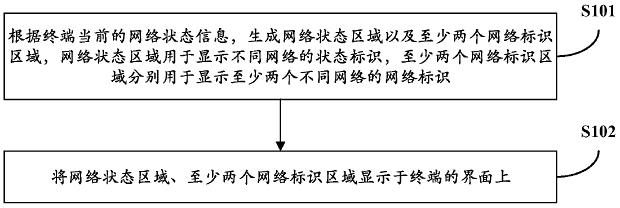
[0060] Such as figure 1 It is a flow chart of the network status display method provided by Embodiment 1 of the present invention, as shown in figure 1 As shown, it should be noted that this method is mainly applied to the multi-mode single-standby mode, and mainly involves network status display when changes occur between networks. The network status display method includes:
[0061] S101: According to the current network status information of the terminal, generate a network status area and at least two network identification areas, the network status area is used to display the status identification between different networks, and the at least two network identification areas are respectively used to display at least two different the network identity of the network;
[0062] Specifically, in order to dynamically display network changes, a set of independent signal display methods is added to the terminal interface, and a network status area and at least two network identi...
Embodiment 2
[0088] Such as Figure 5 A schematic structural diagram of a terminal provided in Embodiment 2 of the present invention, as shown in Figure 5 As shown, the terminal includes:
[0089] The processing module 1 is configured to generate a network status area and at least two network identification areas according to the current network status information of the terminal, the network status area is used to display status identifications between different networks, and at least two network identification areas are used to display Network identities of at least two different networks;
[0090] The display module 2 is configured to display the network status area and at least two network identification areas generated by the processing module 1 on the interface of the terminal.
[0091] Preferably, the display module 2 is specifically configured to sequentially display at least two network identification areas generated by the processing module 1 in the tray area above the interfa...
Embodiment 3
[0098] Such as Figure 6a , 6b , 6c is a schematic diagram of the network switching display provided by Embodiment 3 of the present invention, such as Figure 6a , 6b , 6c, this embodiment is mainly aimed at the network fallback process in the CSFB technology, that is, the process of switching from a 4G network to a 2G network.
[0099] Such as Figure 6a As shown, the network that the terminal is currently connected to is a 4G network, and the network that is not connected is a 2G network. According to the current network status of the terminal, the 4G network logo and its signal strength, the 2G network logo and its signal strength are displayed in the network logo area. In the tray above the terminal interface, the signal strength of the 2G network is displayed as 0, so that the user can intuitively view the current network situation;
[0100] Such as Figure 6b As shown, when the terminal needs to make a voice call, the network state changes, and it needs to fall back...
PUM
 Abstract
Description
Claims
Application Information
 - Generate Ideas
- Intellectual Property
- Life Sciences
- Materials
- Tech Scout
- Unparalleled Data Quality
- Higher Quality Content
- 60% Fewer Hallucinations
Browse by: Latest US Patents, China's latest patents, Technical Efficacy Thesaurus, Application Domain, Technology Topic, Popular Technical Reports.
© 2025 PatSnap. All rights reserved.Legal|Privacy policy|Modern Slavery Act Transparency Statement|Sitemap|About US| Contact US: help@patsnap.com


