
Electrical equipment cabinet

A technology for power cabinets and cabinets, applied in the cooling/ventilation direction of substations/switchgears, can solve problems such as poor heat dissipation of electrical components, and achieve the effects of avoiding poor heat dissipation, solving poor heat dissipation, and reducing power outages.

Active Publication Date: 2014-12-24
STATE GRID CORP OF CHINA +2
View PDF9 Cites 9 Cited by
  • Summary
  • Abstract
  • Description
  • Claims
  • Application Information

AI Technical Summary

Problems solved by technology

[0003] The purpose of the present invention is to provide a power cabinet, which aims to solve the problem of poor heat dissipation of electrical components caused by the natural air-cooled heat dissipation method of the existing cabinet body

Method used


Image

  • Electrical equipment cabinet
  • Electrical equipment cabinet
  • Electrical equipment cabinet

Examples


Embodiment Construction

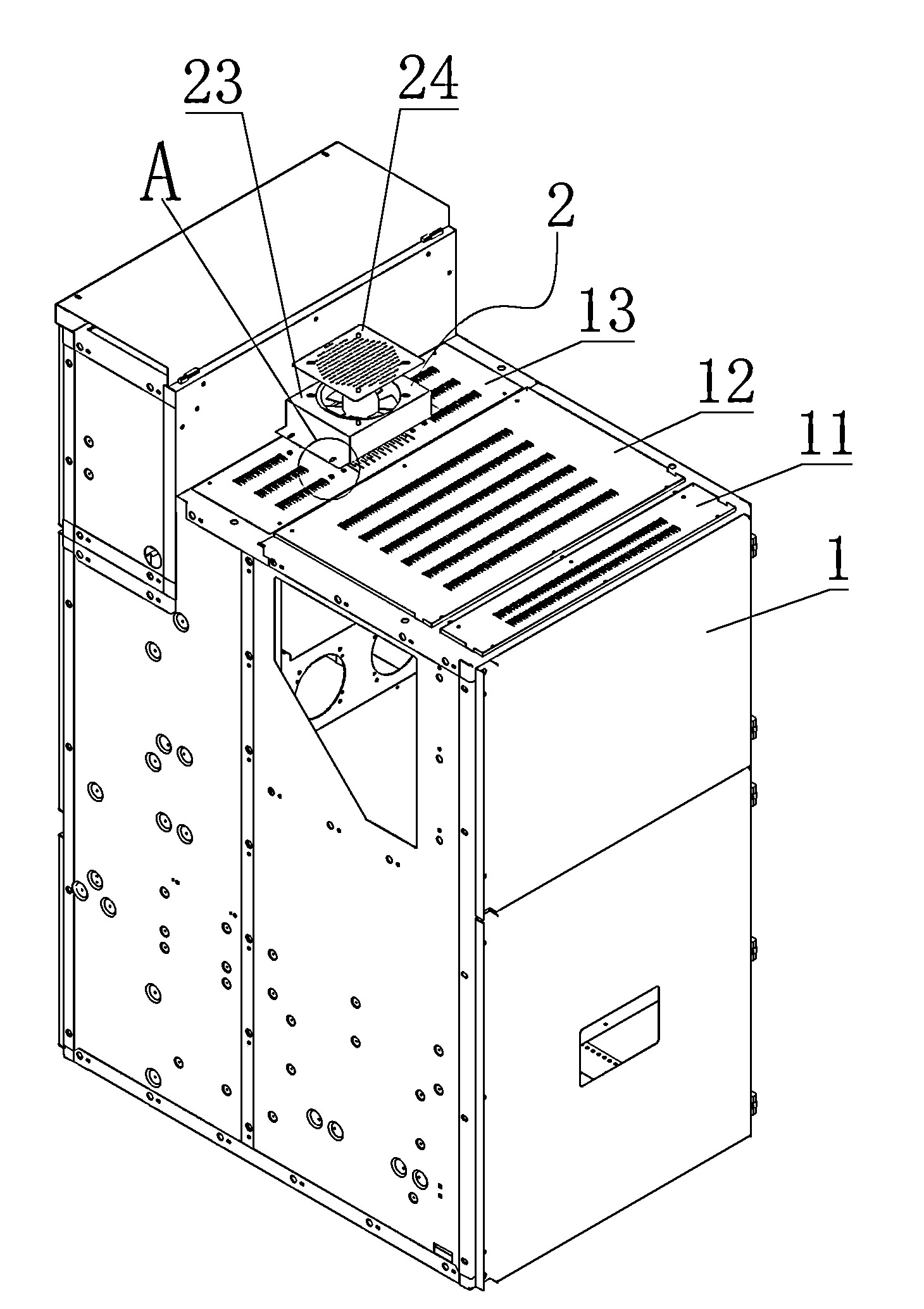
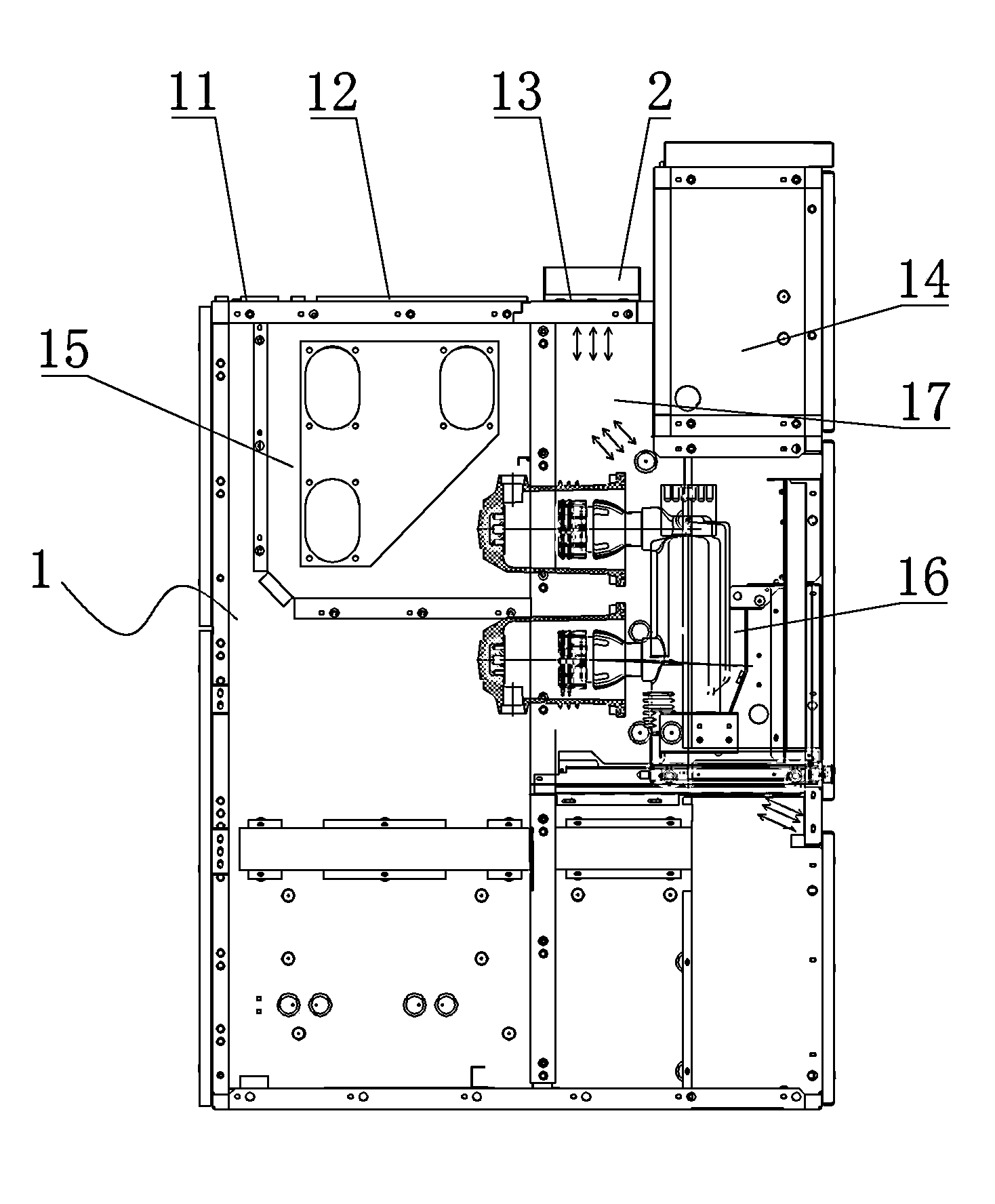
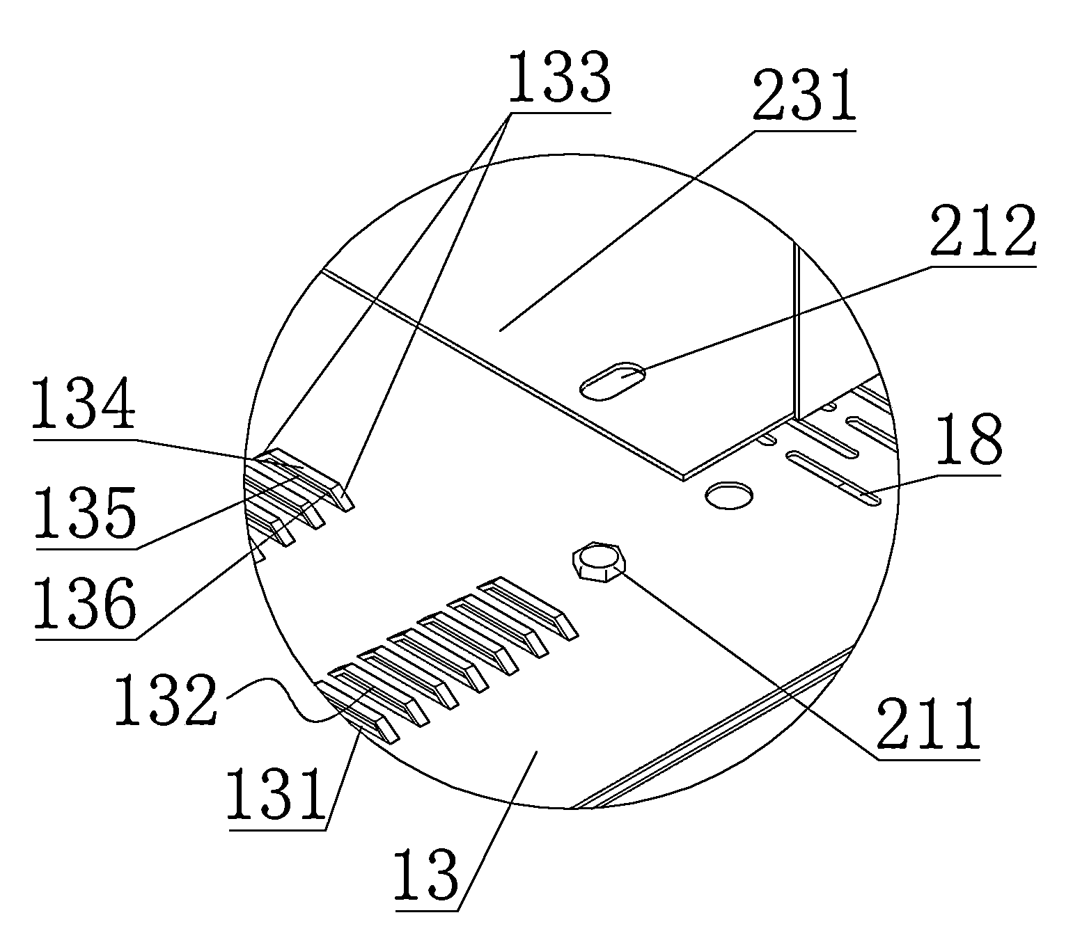
[0025] The embodiment of power cabinet among the present invention: as Figure 1 to Figure 8 As shown, the power cabinet is a high-voltage electrical cabinet, which includes a cabinet body and a fan 2 assembled on it. The cabinet body is composed of a main cabinet body 1 and a pressure relief cover plate. There are three pressure relief cover plates from left to The right side is divided into left pressure relief cover plate 11, middle pressure relief cover plate 12 and right pressure relief cover plate 13 in turn, left pressure relief cover plate 11, middle pressure relief cover plate 12 and right pressure relief cover plate 13 are all subjected to explosion The safety bolts that can be pulled off at any time are fixed on the top of the main cabinet body 1, and are buckled on the pressure relief port opened on the top of the main cabinet body 1, and on the left pressure relief cover plate 11, the middle pressure relief cover plate 12 and the right pressure relief The heat dis...


PUM


Abstract

The invention discloses an electrical equipment cabinet. A cabinet body is provided with a fan and vent holes, wherein the fan is detachably fixed to the exterior of the cabinet body through a thread fastening structure, and the outlet of the fan and the interior space of the cabinet body are communicated through the vent holes. The thread fastening structure comprises fixing nut fixedly or integrally arranged on the cabinet body, bolt-via holes which are formed in the fan and correspond to internal thread holes of the nuts, and fastening bolts matched with the fixing nuts. Thus, by means of the fan, forced air cooling of electrical elements in the cabinet body is achieved, the speed of convective heat exchange between cold air in the exterior space of the cabinet body and hot air in the interior space of the cabinet body is increased, all the electrical elements in the cabinet body are fully cooled, the problem that local cooling inside the cabinet body is unsmooth is avoided, and therefore the problem that due to the natural air cooling mode adopted in the cabinet body, the electrical elements can not be smoothly cooled in the prior art is solved.

Description

technical field [0001] The invention relates to an electric cabinet. Background technique [0002] At present, the natural air cooling method is usually used for heat dissipation on the power cabinet, that is, waist-shaped cooling holes are provided on the cabinet body of the power cabinet, so that the high-temperature air and low-temperature air in the internal and external spaces of the cabinet can convect and play a role in cooling. The effect of air cooling and heat dissipation of electrical components in the cabinet. For example, a central cabinet disclosed in Chinese patent document CN202217939U includes a cabinet body, which is provided with a circuit breaker room, a cable room, a main bus room and an instrument room separated by partitions, and the cabinet body is equipped with a The cabinet doors corresponding to the circuit breaker room, cable room, main bus room and instrument room. Located on the rear side of the middle and upper part of the cabinet, an isolati...

Claims


Application Information

Patent Timeline
Patent Type & Authority Applications(China)
IPC IPC(8): H02B1/56
Inventor 张桂如王皓翔杜永平高颖旭张香芍王华伦王军强
Owner STATE GRID CORP OF CHINA
Learn More