
fluid transmission

A technology for fluid transmission and transmission components, applied in fluid transmission, transmission, vibration suppression adjustment, etc., can solve the problems of increased number of components, increased weight, increased cost, etc.

Active Publication Date: 2017-04-26
HONDA MOTOR CO LTD +2
View PDF7 Cites 4 Cited by
  • Summary
  • Abstract
  • Description
  • Claims
  • Application Information

AI Technical Summary

Problems solved by technology

[0005] However, in the torque converter of the above-mentioned Patent Document 1, in order to connect the two damper mechanisms, dedicated parts are required.
In addition, in order to provide the above-mentioned stopper mechanism, dedicated parts are required
Due to these circumstances, the number of components is greatly increased, causing problems such as increased cost and increased weight

Method used


Image

  • fluid transmission
  • fluid transmission
  • fluid transmission

Examples


Embodiment Construction

[0019] (Structure of torque converter)

[0020] The structure of the torque converter 10 according to the embodiment of the fluid power transmission device of the present invention will be described.

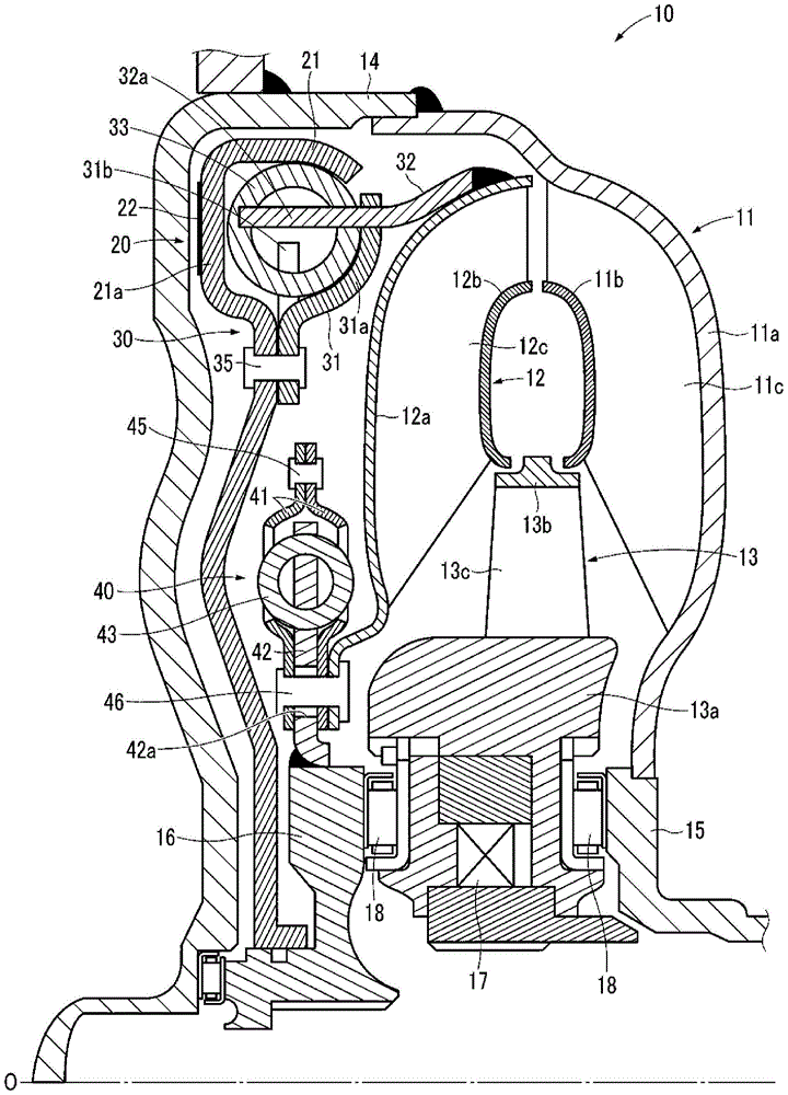
[0021] Such as figure 1 As shown, the torque converter 10 has a shroud 14 and three types of impellers, namely, a pump impeller 11 , a turbine 12 and a stator 13 . An annular passage for circulating hydraulic oil is formed by the pump impeller 11 , the turbine wheel 12 and the stator 13 .

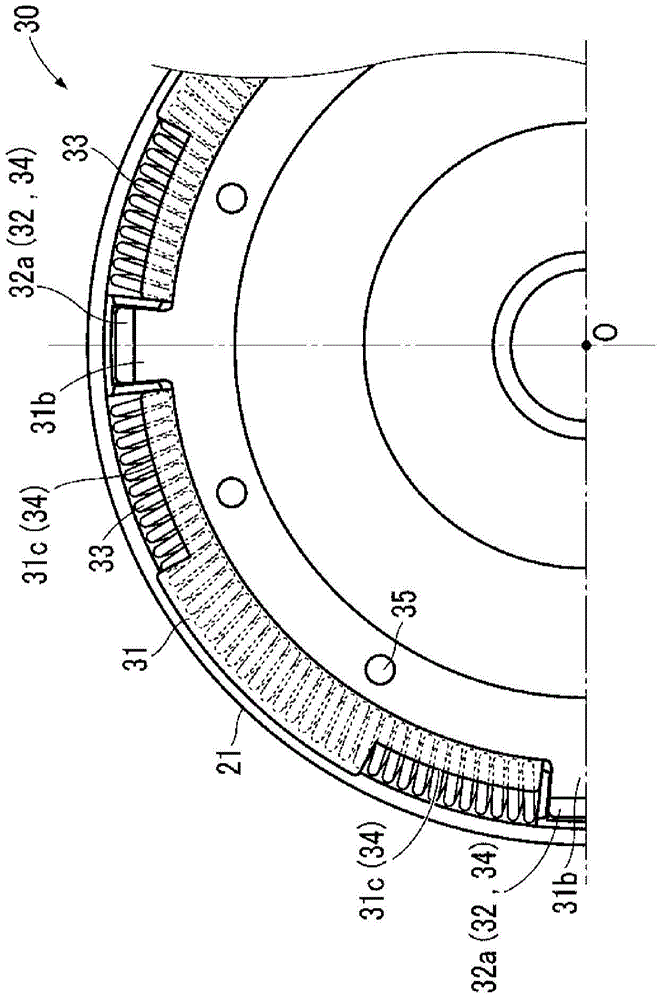
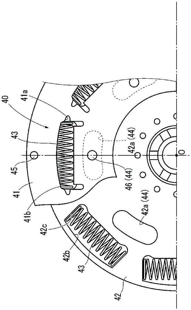
[0022] The torque converter 10 further includes a lock-up clutch 20 and two damper mechanisms 30 and 40 arranged between the turbine wheel 12 and the cover 14 .

[0023] The pump impeller 11 is fixed to the cover 14 by welding. The cover 14 is connected to an unshown drive shaft (engine crankshaft) to which a drive force from a drive source such as an unshown engine is transmitted, and rotates around a center axis O as the drive shaft rotates.

[0024] The turbine 12 is disposed opposite ...


PUM


Abstract

The invention provides a fluid transmission device which can connect two damping mechanisms in a condition that the quantity of components is not greatly increased and which can enable a backstop mechanism to be arranged. As a solution means, a torque converter (10) is provided with two damping mechanisms (30, 40) which are in series connection through a worm (12). In the first damping mechanism (30), through a cut portion (31c) forming in a first holding plate (31), movement of a transmission claw (32) fixed on the worm (12) is limited. In the second damping mechanism (40), through a through hole (42a) forming in an output side plate (42), movement of a rivet (46) connecting the worm (12) and a second holding plate (41) is limited.

Description

technical field [0001] The present invention relates to fluid transmission devices. Background technique [0002] A fluid transmission is a device that temporarily converts the rotational power generated by the driving force from the drive source into fluid kinetic energy, and then converts it back into rotational power and transmits it to the driven shaft. As one type of such a fluid transmission device, a torque converter used in vehicles such as automobiles is known. In a typical torque converter, the engine corresponds to the drive source, and the input shaft of the transmission corresponds to the driven shaft. [0003] In order to reduce torque fluctuations transmitted from the engine to the transmission, a damping mechanism is built into the torque converter. In order to effectively reduce the torque fluctuation, it is only necessary to lower the elastic constant of an elastic body such as a spring constituting the damper mechanism. In order to reduce the elastic co...

Claims


Application Information

Patent Timeline
Patent Type & Authority Patents(China)
IPC IPC(8): F16H45/02F16F15/137
CPCF16F15/137F16H45/02
Inventor 薄井友彦尾梶智哉加藤真志深田纯一
Owner HONDA MOTOR CO LTD
Learn More