Replacement device and method for filler of empty hole part of bored pile

A technology for bored piles and fillers, which is applied to sheet pile walls, buildings, infrastructure engineering, etc. And safety, does not affect the construction period, the effect of simple construction

Active Publication Date: 2014-12-24
CHINA FIRST METALLURGICAL GROUP
View PDF3 Cites 2 Cited by
  • Summary
  • Abstract
  • Description
  • Claims
  • Application Information

AI Technical Summary

Problems solved by technology

With the development of buildings, due to various structural and technical requirements, the pile top elevation of some bored piles is often buried at a deeper position below the surface. For example, before the construction of some deep foundation pits, the hollow part of the engineering pile reached 10m. to more than 20m, so the deep hole above the pile top is prone to hole collapse when drilling adjacent piles. At present, the method of backfilling sand and soil is generally used, but for the hole depth is large, plus The specific gravity of the mud in the hole is relatively large, and it is difficult to fill the lower part of the hole with sand and soil, which cannot meet the requirements of filling. Therefore, for the stratum with poor geological conditions, the normal construction of the adjacent pile hole of the pile cannot be satisfied, and the equipment is prone to collapse. Dumping and other hazards

Method used


Image

  • Replacement device and method for filler of empty hole part of bored pile
  • Replacement device and method for filler of empty hole part of bored pile
  • Replacement device and method for filler of empty hole part of bored pile

Examples


Embodiment 1

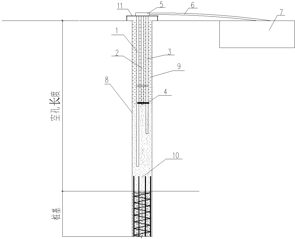
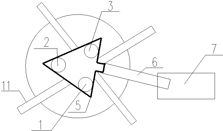
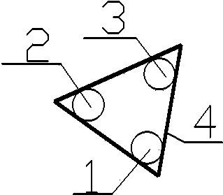
[0029] Such as Figure 1 to Figure 3 As shown, it is a diagram of the use state of a replacement device for filling the hollow part of bored piles provided by Embodiment 1 of the present invention. The empty hole 8 length among the present embodiment is 15-20 meter. The replacement device includes a first guide pipe 1 , a second guide pipe 2 , a third guide pipe 3 , a fixing frame 4 , a guide tank 5 , a hose 6 , a bracket 11 and a mud pool 7 . The bracket 11 is used to fix the ends of the three draft pipes close to the ground. In this embodiment, the bracket 11 is in the shape of a cross. The ends of the three guide pipes close to the ground communicate with the guide groove 5 . One end of the hose 6 is connected to the diversion tank 5 , and the other end of the hose 6 is connected to the mud pool 7 . The fixing bracket 4 is used to fix the bottoms of the first flow guide tube 1 , the second flow guide tube 2 and the third flow guide tube 3 . Fixture 4 is made of steel b...

Embodiment 2

[0036] This embodiment is roughly the same as Embodiment 1, except that the length of the empty holes in this embodiment is 25-30 meters, and the number of draft pipes is five.

Embodiment 3

[0038] This embodiment is roughly the same as Embodiment 1, except that the length of the empty holes in this embodiment is 20-25 meters, and the number of draft pipes is four.


PUM


Abstract

The invention provides a replacement device and method for a filler of an empty hole part of a bored pile. The device comprises n flow guide pipes, a flow guide trench, a bracket, a flexible pipe and a mud pit, wherein n is 1 when the length of the empty hole is 8-10 m; n is 2 when the length of the empty hole is 10-15 m; n is 3 when the length of the empty hole is 15-20 m; n is 4 when the length of the empty hole is 20-25 m; n is 5 when the length of the empty hole is 25-30 m; the bracket is used for fixing the end parts, close to the ground, of the n flow guide pipes; the end parts, close to the ground, of the n flow guide pipes are communicated with the flow guide trench; one end of the flexible pipe is connected with the flow guide trench, and the other end of the flexible pipe is connected with the mud pit. After the n flow guide pipes of different lengths are placed in the empty hole, sandy oil is used as the filler and fills the empty hole to replace mud in the hole so as to realize compact filling in the empty hole and certain strength and guarantee the quality and the safety of the subsequent construction; the device and the method have the advantages of easiness and convenience in construction, low cost, no influence on the construction period, obvious effect and energy conservation and environment protection effects.

Description

technical field [0001] The invention relates to the field of construction, in particular to a device and method for replacing fillers in holes of bored cast-in-place piles. Background technique [0002] Bored pile is a kind of pile foundation widely used in industrial and civil buildings, roads and bridges and other projects. With the development of buildings, due to various structural and technical requirements, the pile top elevation of some bored piles is often buried at a deeper position below the surface. For example, before the construction of some deep foundation pits, the hollow part of the engineering pile reached 10m. to more than 20m, so the deep hole above the pile top is prone to hole collapse when drilling adjacent piles. At present, the method of backfilling sand and soil is generally used, but for the hole depth is large, plus The specific gravity of the mud in the hole is relatively large, and it is difficult to fill the lower part of the hole with sand and...

Claims


Application Information

Patent Timeline
Patent Type & Authority Applications(China)
IPC IPC(8): E02D5/34
Inventor 黎明中李卓罗劲张继明任若微
Owner CHINA FIRST METALLURGICAL GROUP
Why Eureka
Try Eureka