
Shoe upper computer sewing machine

A sewing machine and computer technology, applied in the field of sewing processing, can solve problems such as inability to guarantee the service life, inability to hold down the workpiece, inability to complete tasks, etc., and achieve the effects of saving raw materials, improving production efficiency, and accurate stitching

Active Publication Date: 2014-12-24
盐城市鑫亚机械有限公司
View PDF6 Cites 5 Cited by
  • Summary
  • Abstract
  • Description
  • Claims
  • Application Information

AI Technical Summary

Problems solved by technology

[0003] At present, computerized lockstitch sewing machines and embroidery machines cannot sew shoe uppers very well.
The reason is that in the existing equipment: ①The mobile platform supports the workpiece with cloth or the like as a board surface to carry the workpiece, which cannot guarantee the service life for the graphics that use the same track for a long time, and the workpiece shakes up and down during the processing process, front and rear, left and right chatter, making processing inaccurate
②In the existing equipment, the workpieces are fixed by adhesive tape or the like. One by one operation is complicated, wastes materials, and the efficiency is low. It is difficult to fix our workpieces.
③Pressure foot of existing equipment Some adopt the roller type, but if the needle running track (relative to the workpiece) is a non-linear line such as a curve or a circle when sewing, the rolling direction of the roller and the direction of the needle movement cannot be consistent
If the seam is curved or round, the same as The task cannot be completed as described
Some presser feet press the workpiece by random needle movement up and down, which solves the problem However, the workpiece cannot be pressed down before the needle penetrates into the workpiece, nor can it be pressed down when the needle is pulled out of the workpiece, causing the workpiece to shake up and down when the needle reciprocates into and out of the workpiece.
Therefore, the suture stitches deviate from the correct track, making the stitches unattractive, resulting in large processing deviations

Method used


Image

  • Shoe upper computer sewing machine
  • Shoe upper computer sewing machine
  • Shoe upper computer sewing machine

Examples


Embodiment Construction

[0019] In order to make the technical means, creative features, goals and effects achieved by the present invention easy to understand, the present invention will be further described below in conjunction with specific embodiments.

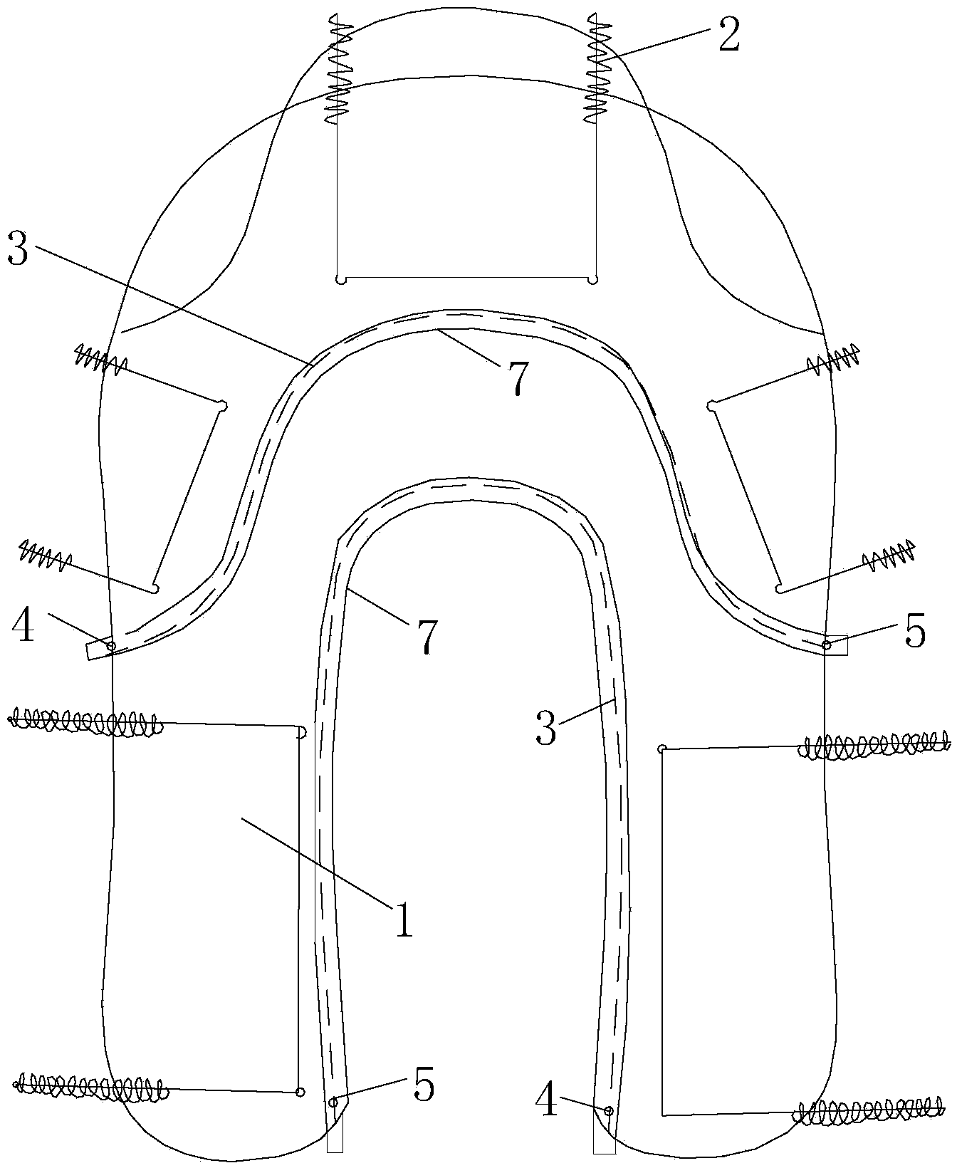
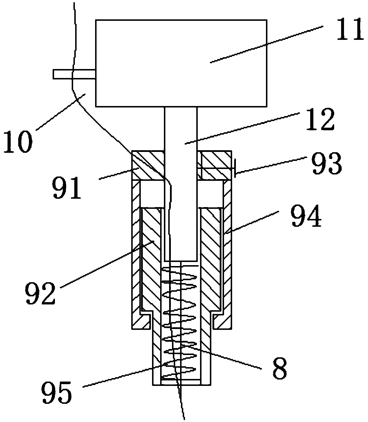
[0020] refer to Figure 1-5 , the specific embodiment adopts the following technical solutions: shoe upper computer sewing machine, including steel wire spring clamp 2, stitches 3, starting point 4, end point 5, stitch template 6, stitch channel 7, stitches are arranged under the shoe upper fabric 1 Template 6, the stitch template 6 is provided with a stitch channel 7, the stitch channel 7 is provided with a stitch 3, the beginning and the end of the stitch 3 are the starting point 4 and the end point 5 respectively, and the shoe upper fabric 1 is fixed on the On the moving platform of the sewing machine; the outer ring of the stitch channel 7 is provided with a plurality of work limiting panels 61 , and the four corners of the stitch template 6 a...


PUM


Abstract

The invention discloses a shoe upper computer sewing machine. The shoe upper computer sewing machine comprises steel wire spring clamps, stitches, starting points, ending points, stitch templates and stitch through grooves, wherein the stitch templates are arranged below shoe side fabrics; the stitch through grooves are formed in the stitch templates; the stitches are arranged in the stitch through grooves; the starting points and the ending points are arranged on the heads and the tails of the stitches; the shoe upper fabrics are fixed on a sewing machine motion platform through a plurality of steel wire spring clamps. The shoe upper computer sewing machine has the advantages of simple structure and good sewing effect, and a sewn shoe upper pattern is high in consistence; moreover, a plurality of machines can be operated simultaneously, so that the production efficiency is increased greatly.

Description

technical field [0001] The invention relates to the field of sewing processing, in particular to a computerized sewing machine for shoe uppers. Background technique [0002] When the traditional computer sewing machine sews shoes, due to the poor fixing effect, it is easy to produce misalignment, and the patterns sewn by different shoe sizes are not the same, resulting in defective products, which greatly reduces the efficiency and efficiency of shoe upper sewing. quality. At present, the stitching of the upper in the shoemaking industry all adopts the working method that the motor is driven to control the stitches by manual feeding. This has just caused the quality of sewing products to be unstable and the production efficiency to be low. [0003] At present, computerized lockstitch sewing machines and embroidery machines cannot sew vamps well. The reason is that in the existing equipment: ①The mobile platform supports the workpiece with cloth or the like as the board su...

Claims


Application Information

Patent Timeline
Patent Type & Authority Applications(China)
IPC IPC(8): D05B15/02D05B29/04D05B29/06
Inventor 陈卡丹
Owner 盐城市鑫亚机械有限公司
Learn More