Manufacturing method of centrifugal vapor compressor diffuser

A technology for steam compressors and manufacturing methods, which is applied in the field of centrifugal steam compressors, and can solve problems affecting the accuracy of lathes, large tool wear, poor verticality, etc., and achieve the effects of improving processing efficiency, removing local deformation, and improving verticality

Active Publication Date: 2014-12-24
CHONGQING JIANGJIN SHIPBUILDING IND
View PDF5 Cites 11 Cited by
  • Summary
  • Abstract
  • Description
  • Claims
  • Application Information

AI Technical Summary

Problems solved by technology

[0005] Aiming at the technical problems of poor diffuser blade profile and poor verticality between the end face and the positioning hole in the prior art; further, in the prior art, the connection hole is processed first and then the end face is turned, intermittent cutting Leading to technical problems such as low efficiency, large tool wear and affecting the precision of lathes, the present invention provides a manufacturing method for a diffuser of a centrifugal steam compressor, through rough milling of the blade flow channel, removing a large margin, then semi-finish milling, and finally Fine milling of the vane flow channel reduces the deformation of the diffuser after milling the vane, avoids the impact on the subsequent process, and improves the profile of the diffuser's blade profile and the verticality between the end face and the positioning hole; In addition, only two positioning holes are processed on the end face of the semi-finishing and finishing turning, which improves the processing efficiency and reduces the wear on the tool when semi-finishing and finishing the end face

Method used


Image

  • Manufacturing method of centrifugal vapor compressor diffuser
  • Manufacturing method of centrifugal vapor compressor diffuser
  • Manufacturing method of centrifugal vapor compressor diffuser

Examples


Embodiment Construction

[0040] The specific implementation manner of the present invention will be described in further detail below in conjunction with the accompanying drawings.

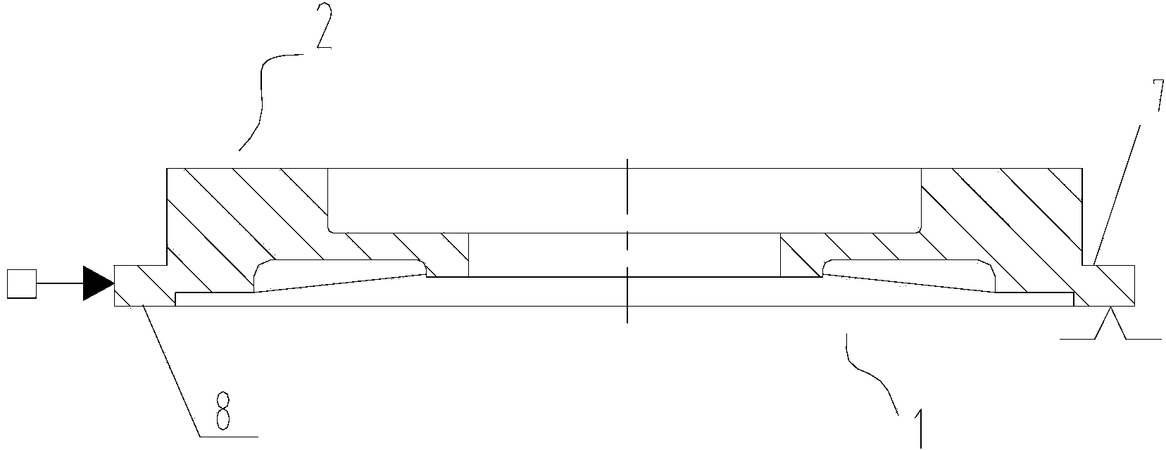
[0041] Such as Figure 1-7 Shown, the manufacture method of centrifugal vapor compressor diffuser of the present invention, comprises the following steps:

[0042] a. Blank heat treatment;

[0043] b. The end face, outer circle, inner hole and second step end face 9 of the large end 1 of the rough turning diffuser;

[0044] c. The end face, outer circle, inner hole and first step end face 7 of the small end 2 of the rough car diffuser;

[0045] d. Drill a positioning hole for milling on the edge of the end face of the big end 1, install the milling tool, and position through the positioning hole, rough mill the blade 3 on the small end 2;

[0046] e. The end face, outer circle, inner hole and first step end face 7 of the small end 2 of the semi-finished car diffuser;

[0047] f. The end face, outer circle, inner hole ...


PUM


Abstract

The invention provides a manufacturing method of a centrifugal vapor compressor diffuser. The method comprises the following steps: performing heat treatment on a blank; roughly turning the end surface, excircle, inner bore and second step end surface of a large end of a diffuser; roughly turning the end surface, excircle, inner bore and first step end surface of a small end of the diffuser; drilling and milling a locating hole in the edge of the end surface of the large end, mounting a milling tool, locating by virtue of the locating hole, and roughly milling a blade on the small end; performing half finish turning on the end surface, excircle, inner bore and first step end surface of the small end of the diffuser; performing half finish turning on the end surface, excircle, inner bore and second step end surface of the large end of the diffuser; mounting a milling tool, locating by virtue of the locating hole, performing fine milling on the blade, and delivering the product into a coordinate measuring machine for inspection after fine milling is finished; if the product is qualified, marking center lines for drilling on the end surfaces of the large and small ends and the first step end surface; aligning the center liens; drilling and threading; finely turning the end surface and inner bore of the large end of the diffuser; performing draw filing on the bottom of a blade passage; performing penetrant inspection on the blade.

Description

technical field [0001] The invention relates to the field of centrifugal steam compressors, in particular to a method for manufacturing a diffuser of a centrifugal steam compressor. Background technique [0002] The centrifugal steam compressor is an energy-saving technology that reuses the energy of the secondary steam generated by itself, thereby reducing the demand for external energy. The centrifugal steam compressor is the key equipment for the heat recovery system to increase the steam pressure by compressing the fresh steam generated. Its working principle is: the compressor impeller rotates on the shaft of the compressor, the gas entering the compressor impeller is rotated, and then enters the diffuser, where the speed of the gas is converted into the required pressure. In recent years, with the increasing emphasis on energy conservation, centrifugal steam compressors have been more widely used. [0003] The centrifugal steam compressor consists of two parts, the r...

Claims


Application Information

Patent Timeline
Patent Type & Authority Applications(China)
IPC IPC(8): B23P15/00
CPCB23P15/00
Inventor 段昌文柯益徐海燕罗兵
Owner CHONGQING JIANGJIN SHIPBUILDING IND
Why Eureka
Try Eureka